
Data Sheet

ROBOT . HEAD to TOE
Product User’s Manual – URC10
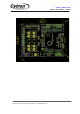
5. INSTALLATION (HARDWARE)
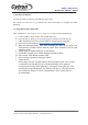
5.1 Connecting Driver to a DC Motor
URC10 is compatible with 2 types of PWM operation, which are:
1. Sign-Magnitude PWM - For sign-magnitude PWM operation, 2 control signals are used to
control the speed and direction of the motor. PWm is feed to the PWM pin to control the speed
while DIR pin is used to control the direction.
2. Locked-Antiphase PWM - For locked-antiphase PWM operation, only 1 control signal is
needed to control the speed and direction of the motor. PWM pin is connected to logic high while
the DIR pin is being feed with the PWM signal. When the PWM signal has 50% duty cycle, the
motor stops running. If the PWM has less than 50% duty cycle, the motor will turn CW(or CCW
depending on the connection). If the PWM signal has more than 50% duty cycle, motor will turn
CCW(or CW depending on the connection)
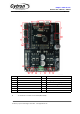
Sample connection diagram is as follow:
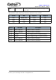
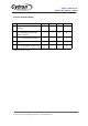
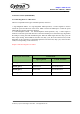
URC10 pin control name
Control Mode
Sign magnitude
Locked Anti-Phase
DIR1 (pin 4)
Direction control
Enable driver
PWM1 (pin 5)
Speed Control
Speed & Direction
PWM2 (pin 6)
Speed control
Speed & Direction
DIR2 (pin 7)
Direction control
Enable driver
.
Created by Cytron Technologies Sdn. Bhd. – All Rights Reserved