
Data Sheet

ROBOT . HEAD to TOE
Product User’s Manual – URC10
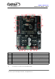
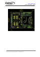
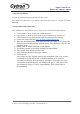
B – A 2 ways connector for user to connect particular DC motor. Please skru the
wire properly by referring to chapter 5, Hardware Installation.
C – Red LEDs acting as indicator for motor direction These LEDs will indicate
which direction is being powered at a moment
.
D – ICSP connector/ SPI conection
E – USB for UART communication between URC10 and PC’s Serial
Communication Interface (SCI).
F – A push button acting as reset button to URC10. If this button is pressed, URC10 will
be reset to initial stage. Please DO NOT pressed this button during operation
.
G – A push button to activate self test on URC10. When it is pressed and hold, URC10 will
start to drive stepper motor. If power supply is connected and this button is pressed,
LEDs at C will illuminate sequentially.
H – A small green LED to indicate status of power. If power is connected,
this LED will light ON.
I – Voltage input for the power source.
J – A 6x3 ways connector for analog input complete with Signal, 5V and GND pin.
K – A 4x3 ways connector for Digital IO complete with Signal, 5V and GND pin.
L – A 4x1 ways connector for user to connect particular SPI/I2C device
.
M – A 8x1 ways connector for power extension, normally not use.
N – A jumper at back of PCB is to to select power for I2C/SPI device
Created by Cytron Technologies Sdn. Bhd. – All Rights Reserved