2x10A UNO ROBOT CONTROLLER URC10 User’s Manual V1.
ROBOT . HEAD to TOE Product User’s Manual – URC10 Index 1. Introduction and Overview 3 1.0 Introduction of UNO Robot Contoller (URC10) 3 1.1 System Overview 4 1.2 General Description 5 2. Packing List 6 3. Product Specification and Limitations 7 4. Board Layout 9 4.1 Dimension 5. Installation (hardware) 10 11 5.1 Connecting Driver to a DC Motor 11 5.2 Connecting to URC10 using Signal Input Pin (HC-SR04) 13 6. Installation Driver 21 7. Getting Started 25 7.
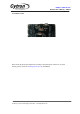
ROBOT . HEAD to TOE Product User’s Manual – URC10 INTRODUCTION AND OVERVIEW 1.0 Introduction of UNO Robot Controller (URC10) 2x10A UNO Robot Controller is designed to drive two high current brushed DC motor up to 10A continuously by using build in CT-UNO as a controller. This board combines the simplicity of the UNO’s Optiboot bootloader (which load program faster), and the R3 shield compatibility of the latest Arduino UNO R3 with motor driver that can drive 10A continuously.
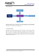
ROBOT . HEAD to TOE Product User’s Manual – URC10 1.1 System Overview Uno Robot Controller is one of motor driver with built in controller. One of the additional features for URC10 compare to other driver is the I/O extension pin and interface for easiest communication or connect directly to Arduino Shield. . 1.2 General Description Driving brush motor is common necessity in most robotic project. A brush motor is a electric motor that can drive a full rotation.
ROBOT . HEAD to TOE Product User’s Manual – URC10 2. PACKING LIST Please check the parts and components according to the packing list. If there are any parts missing, please contact us at sales@cytron.com.my immediately. Created by Cytron Technologies Sdn. Bhd.
ROBOT . HEAD to TOE Product User’s Manual – URC10 Mobility Uno comes with: • 1 x Mobility Uno board with every component is soldered properly and tested before board is shipped. • User’s Manual and sample Arduino sketch can be downloaded from http://www.cytron.com.my/p-URC10. Created by Cytron Technologies Sdn. Bhd.
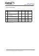
ROBOT . HEAD to TOE Product User’s Manual – URC10 3. PRODUCT SPECIFICATION AND LIMITATIONS Power Input Pins Function Description Label VM Definition Motor Supply Voltage Function VM is for board power sources. VM will supplies power to both motor and controller circuit. User must ensure the voltage and polarity of connection are correct before providing the power so that Mono can function correctly. GND System Ground Common ground for both logic operation and stepper motor power source.
ROBOT . HEAD to TOE Product User’s Manual – URC10 GND System Ground Common ground for both logic operation and stepper motor power source.
ROBOT . HEAD to TOE Product User’s Manual – URC10 Absolute Maximum Rating No 1 Parameter Max Typical Min Unit Input Voltage (Motor Supply Voltage) 7 - 24 V 2 IMAX (Maximum Continuous Motor Current)* - - 10 A 3 IPEAK – (Peak Motor Current) ** - - 30 A 4 VIOH (Logic Input – High Level) 5 - 1.3 V 5 VIOL (Logic Input – Low Level) 0.7 - 0 V * For momentary peak current. Driving at this condition may trigger overheat or over-current cut-off. **Must not exceed 1 second.
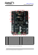
ROBOT . HEAD to TOE Product User’s Manual – URC10 4.BOARD LAYOUT Label A B C D E F G A Function Connector for Sonar Connector to Motor Small LED as indicator ICSP connector USB connector for Arduino Push button to reset Push button to test Label H I J K L M N Function Small LED as POWER indicator Voltage input (7V-24V) Connector for analog input Connector for Digital IO Connector for LCD Power extension Power select – A connector to connect to two Sonar(HC-SR04) . Created by Cytron Technologies Sdn.
ROBOT . HEAD to TOE Product User’s Manual – URC10 B – A 2 ways connector for user to connect particular DC motor. Please skru the wire properly by referring to chapter 5, Hardware Installation. C – Red LEDs acting as indicator for motor direction These LEDs will indicate which direction is being powered at a moment . D – ICSP connector/ SPI conection E – USB for UART communication between URC10 and PC’s Serial Communication Interface (SCI). F – A push button acting as reset button to URC10.
ROBOT . HEAD to TOE Product User’s Manual – URC10 4.1 DIMENSION *All dimension in milimeter. Created by Cytron Technologies Sdn. Bhd.
ROBOT . HEAD to TOE Product User’s Manual – URC10 5. INSTALLATION (HARDWARE) 5.1 Connecting Driver to a DC Motor URC10 is compatible with 2 types of PWM operation, which are: 1. Sign-Magnitude PWM - For sign-magnitude PWM operation, 2 control signals are used to control the speed and direction of the motor. PWm is feed to the PWM pin to control the speed while DIR pin is used to control the direction. 2.
ROBOT . HEAD to TOE Product User’s Manual – URC10 5.2 Connecting to URC10 using Signal Input Pin(HC-SR04) Typical application would require a controller to generate pulses and wait for reflected ultrasonic burst. Following figure shows an example of HC-SR04 connected to URC10. The above example shows that the TRIG pin is connected to pin number D9 and Echo pin connected to pin number D8. Example connection as follow: Created by Cytron Technologies Sdn. Bhd.
ROBOT . HEAD to TOE Product User’s Manual – URC10 6. INSTALLATION DRIVER This board (URC10) use CH340G USB to UART converter as for skecth uploading bridge. This UART chip require USB driver to be installed on computer. Please download the respective driver for your computer or laptop: 1. Windows user 2. MAC OS driver for OSX Mavericks 10.9, Yosemite 10.10, and El Capitan 10.11 3. MAC OS driver for OSX Sierra 10.12 4. Linux normally pre-installed with the proper driver Created by Cytron Technologies Sdn.
ROBOT . HEAD to TOE Product User’s Manual – URC10 7. GETTING STARTED You will need URC10 board and USB Micro B cable to start. This section will show how to get started with URC10 and connect to computer for sketch uploading. 7.1 Using URC10 with Arduino IDE After installation of URC10 driver, user is ready to use URC10 with computer/laptop. A. B. C. D. E. F. G. H. I. J. Connect USB to URC10, another end of USB cable to PC. Power up URC10. When power is connected, power indicator LED will turn ON.
ROBOT . HEAD to TOE Product User’s Manual – URC10 8. WARRANTY ❖ ❖ ❖ ❖ Product warranty is valid for 6 months. Warranty only applies to manufacturing defect. Damage caused by miss-use is not covered under warranty. Warranty does not cover freight cost for both ways. Prepared by Cytron Technologies Sdn. Bhd. 19, Jalan Kebudayaan 1A, Taman Universiti, 81300 Skudai, Johor, Malaysia. Tel: +607-521 3178 Fax: +607-521 1861 URL: www.cytron.com.my Email: support@cytron.com.my sales@cytron.com.