
User Manual

ROBOT.HEADtoTOE
ProductUser’sManual–MD10C
5.GETTINGSTARTED
MD10Ciscompatiblewith2typesofPWMoperation,whichare:
1. SignMagnitude PWM – For signmagnitude PWM operation, 2 control signals are used to
control the speed and direction of the motor. PWM is feed to the PWM pin to control the
speedwhileDIRpinisusedtocontrolthedirectionofthemotor.
2. LockedAntiphase PWM – For lockedantiphase PWM operation, only 1 control signal is
needed to control the speed and direction of the motor. PWM pin is connected to logic high
while the DIR pin is being feed with the PWM signal. When the PWM signal has 50% duty
cycle, the motor stops running. If the PWM has less than 50% duty cycle, the motor will turn
CW (or CCW depending on the connection). If the PWM signal has more than 50% duty
cycle,motorwillturnCCW(orCWdependingontheconnection).
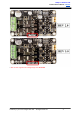
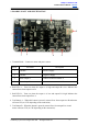
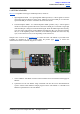
Sample source code for using PIC16F877A to control the motor with MD10C is provided and is
available for download at Cytron’s website under the product page. SK40C is used in the
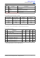
demonstrationandtheconnectiondiagramisasfollow:
1. Connect MD10C and SK40C as shown in the schematic above and select the board supply for
MD10C.
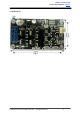
2. Upload the hex file into SK40C using UIC00A/B. The hex file can be downloaded from
Cytron's website under MD10C Sample program. Please refer SK40C or UIC00B User's
ManualtouploadthehexcodeintoSK40C.
CreatedbyCytronTechnologiesSdn.Bhd.–AllRightsReserved 9