
User Manual

ROBOT.HEADtoTOE
ProductUser’sManual–MD10C
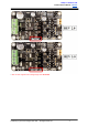
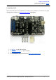
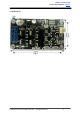
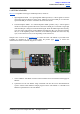
3.BOARDLAYOUTANDSPECIFICATION
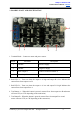
1. TerminalBlock–Connecttomotorandpowersource.
PinNo.
PinName
Description
1
POWER+
PositiveSupply
2
POWER
NegativeSupply
3
MotorOutputA
ConnecttomotorterminalA
4
MotorOutputB
ConnecttomotorterminalB
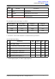
2. Red LED A – Turns on when the output A is high and output B is low. Indicates the
currentflowsfromoutputAtoB.
3. Red LED B – Turns on when the output A is low and output B is high. Indicates the
currentflowsfromoutputBtoA.
4. Test Button A – When this button is pressed, current flows from output A to B and motor
willturnCW(orCCWdependingontheconnection).
5. TestButtonB–Whenthisbuttonispressed,currentflowsfromoutputBtoAand
motorwillturnCCW(orCWdependingontheconnection).
CreatedbyCytronTechnologiesSdn.Bhd.–AllRightsReserved 6