
Manual
ROBOT.HEADtoTOE
ProductUser’sManual–SHIELDMD10
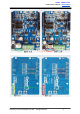
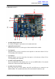
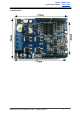
7. ResetButton
ResetbuttonisfortheconvenienceofusertoresettheArduinomainboard.
8. RedLEDB
Turns ON when the output A is low and output B is high. Indicates the current flows from
outputBtoA.
9. RedLEDA.
Turns ON when the output B is low and output A is high. Indicates the current flows from
outputAtoB.
10. GreenPowerLED
TurnonwhentheSHIELDMD10ispoweredup.
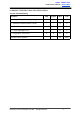
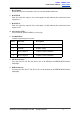
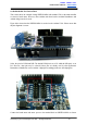
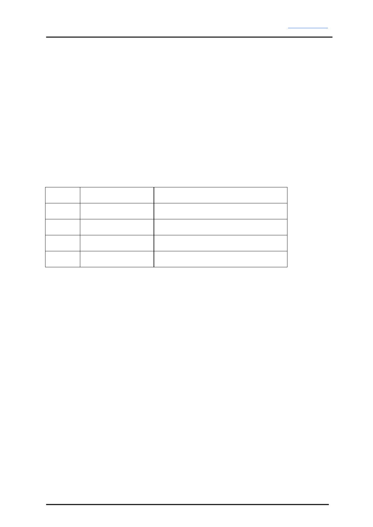
11. TerminalBlock
Connecttomotorandpowersource.
PinNo.
PinName
Description
1
POWER+
Positivesupply
2
POWER
Negativesupply
3
MotorOutputA
ConnecttomotorterminalA
4
MotorOutputB
ConnecttomotorterminalB
12. PWMPinSelector
User may select D3, D5, D6, D9, D10 or D11 as the PWM pin for SHIELDMD10 with the
minijumper.
13. DIRPinSelector
User may select D2, D4, D7, D8, D12 or D13 as the direction pin for SHIELDMD10 with the
minijumper.
CreatedbyCytronTechnologiesSdn.Bhd.–AllRightReserved 8