
Manual
ROBOT.HEADtoTOE
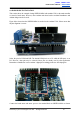
ProductUser’sManual–SHIELDMD10
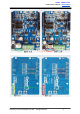
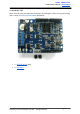
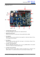
4.0BOARDLAYOUT
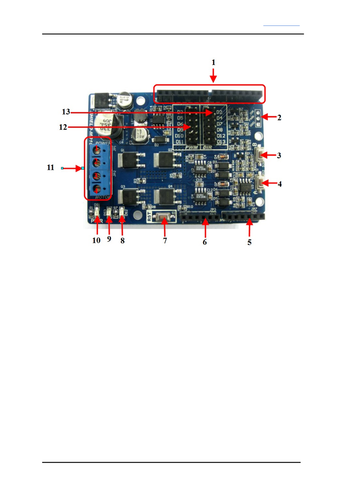
1. StackableDigitalI/OHeaders
JP4andJP6areDigitalI/OpinsstackedtotheArduinomainboard.
2. OptionalExternalControl
ExternalcontrolisfortheuseofothertypesofmicrocontrollerbesidesArduino.
3. TestButtonB
When this button is pressed, current flows from output B to A and motor will turn CCW (or
CWdependingontheconnection).
4. TestButtonA
When this button is pressed, current flows from output A to B and motor will turn CW (or
CCWdependingontheconnection).
5. StackableAnalogInputHeader
This is the analog port of the Arduino and is not used by SHIELDMD10. The stackable
headerallowsotherstackedshieldtoutilizethesepins.
6. StackablePowerPinsHeader
This is the power port of the Arduino. Only RST and GND pins are connected to the
SHIELDMD10.Thestackableheaderallowsotherstackedshieldtoutilizethesepins.
CreatedbyCytronTechnologiesSdn.Bhd.–AllRightReserved 7