
User Manual

Product User’s Manual – RB-Cyt-153 (MDD10A)
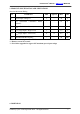
6. Input
Pin No.
Pin Name
Description
1
GND
Ground
2
*PWM2
PWM input for speed control (Motor 2)
3
DIR2
Direction input (Motor 2)
4
*PWM1
PWM input for speed control (Motor 1)
5
DIR1
Direction input (Motor 1)
*Note that it is not for RC PWM
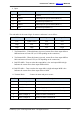
The truth table for the control logic for motor 1 and motor 2 are as follow:
PWM
DIR
Output A
Output B
Low
X(Don’t care)
Low
Low
High
Low
High
Low
High
High
Low
High
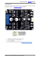
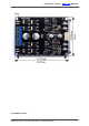
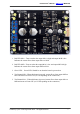
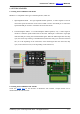
7. Test Button M2A – When this button is pressed, current flows from output M2A to
M2B and motor will turn CW (or CCW depending on the connection).
8. Test Button M2B – When this button is pressed, current flows from output M2B to
M2A and motor will turn CCW (or CW depending on the connection).
9. Red LED M2B – Turns on when the output M2A is low and output M2B is high.
Indicates the current flows from output M2B to M2A.
10. Red LED M2A – Turns on when the output M2A is high and output M2B is low.
Indicates the current flows from output M2A to M2B.
11. Terminal Block – Connect to motor and power source.
Pin No
Pin Name
Description
1
Motor 1 Output B
Connect to motor 1 terminal B
2
Motor 1 Output A
Connect to motor 1 terminal A
3
POWER +
Positive Supply (positive terminal of battery)
4
POWER -
Negative Supply (negative terminal of battery)
5
Motor 2 Output A
Connect to motor 2 terminal A
6
Motor 2 Output B
Connect to motor 2 terminal B
Created by Cytron Technologies Sdn. Bhd. – All Rights Reserved 8