
User Manual

Product User’s Manual – RB-Cyt-153 (MDD10A)
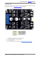
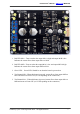
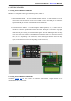
1. Red LED M1A – Turns on when the output M1A is high and output M1B is low.
Indicates the current flows from output M1A to M1B.
2. Red LED M1B – Turns on when the output M1A is low and output M1B is high.
Indicates the current flows from output M1B to M1A.
3. Green LED – Power LED. Should be on when the board is powered on.
4. Test Button M1B – When this button is pressed, current flows from output M1B to
M1A and motor will turn CCW (or CW depending on the connection).
5. Test Button M1A – When this button is pressed, current flows from output M1A to
M1B and motor will turn CW (or CCW depending on the connection).
Created by Cytron Technologies Sdn. Bhd. – All Rights Reserved 7