
User Manual

Product User’s Manual – RB-Cyt-153 (MDD10A)
6. GETTING STARTED
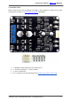
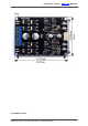
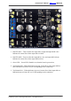
6.1 Getting Started MDD10A with SK40C
MDD10A is compatible with 2 types of PWM operation, which are:
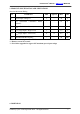
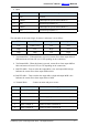
1. Sign-Magnitude PWM – For sign-magnitude PWM operation, 2 control signals are used to
control the speed and direction of the motor. PWM is feed to the PWM pin to control the
speed while DIR pin is used to control the direction of the motor.
2. Locked-Antiphase PWM – For locked-antiphase PWM operation, only 1 control signal is
needed to control the speed and direction of the motor. PWM pin is connected to logic high
while the DIR pin is being feed with the PWM signal. When the PWM signal has 50% duty
cycle, the motor stops running. If the PWM has less than 50% duty cycle, the motor will turn
CW (or CCW depending on the connection). If the PWM signal has more than 50% duty
cycle, motor will turn CCW (or CW depending on the connection).
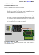
6.2 Getting Started MDD10A with Arduino
Check the tutorial here for the interface of MDD10A with Arduino, example sketch can be
downloaded at the end of tutorial.
Created by Cytron Technologies Sdn. Bhd. – All Rights Reserved 10