
Operating Guide

4
SURFACES.
CAUTION: Tapes may cause discoloration to some surfaces over time. Remove one side of the
tape liner and apply to the bottom of the clips. Apply pressure for 5 seconds to assure adhesion.
Place clips on the lightbars.
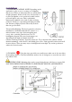
4. LIGHTBAR PLACEMENT Remove the second side of tape liner. Keep the tape surface
clean. Place the bars in the proper location by pressing on the clips for 5 seconds. CAUTION:
Never press on the clear lens of bars. Lightbars will get damaged! Note the direction of the wires
being routed to the hub.
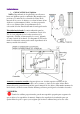
5. HUB Mount the hub using screws
or tapes. Plug the lightbar connectors
into hub outlets. The plugs are
polarized and can only be plugged in
one direction.
6. CONTROLLER Use tape to
mount the controller in an accessible
location. Some painted surfaces may
get damaged upon future removal of
the tape/controller.
7. POWER UP Plug the power
supply into an AC outlet. The plug is
polarized (one blade is wider than the
other) as a feature to reduce the risk
of electric shock. This plug will fit in a polarized outlet only one way. If the plug does not fit
fully in the outlet, reverse the plug. If it still does not fit, contact the factory or a qualified
electrician. Never use with an extension cord unless the plug can be fully inserted. Do not alter
the plug.
8. DC JACK Connect the DC power jack into the controller DC cord.
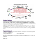
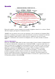
Operations
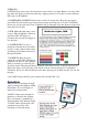
Turn the unit on and adjust the light
angle by twisting the lightbars within
the brackets. Try several angles to
achieve the desired results.
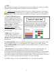
“MODE” button cycles through 14
functions as shown in the diagram.
Press of a button is confirmed by a
short fast blink of the Indicator Light.
“PAUSE” button will stop the color
transition in any of the color
transition or color fade modes.