
Programmable Embedded USB Host and Peripheral Controller with Automotive AEC Grade Support Specification Sheet
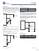
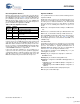
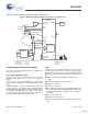
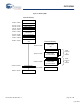
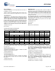
Table Of Contents
- EZ-Host Features
- Typical Applications
- Introduction
- Functional Overview
- Interface Descriptions
- USB Interface
- OTG Interface
- External Memory Interface
- General Purpose IO Interface (GPIO)
- UART Interface
- I2C EEPROM Interface
- Serial Peripheral Interface
- High-Speed Serial Interface
- Programmable Pulse/PWM Interface
- Host Port Interface
- IDE Interface
- Charge Pump Interface
- Booster Interface
- Crystal Interface
- Boot Configuration Interface
- Operational Modes
- Power Savings and Reset Description
- Memory Map
- Registers
- Processor Control Registers
- CPU Flags Register [0xC000] [R]
- Bank Register [0xC002] [R/W]
- Hardware Revision Register [0xC004] [R]
- CPU Speed Register [0xC008] [R/W]
- Power Control Register [0xC00A] [R/W]
- Interrupt Enable Register [0xC00E] [R/W]
- Breakpoint Register [0xC014] [R/W]
- USB Diagnostic Register [0xC03C] [R/W]
- Memory Diagnostic Register [0xC03E] [W]
- External Memory Registers
- Timer Registers
- General USB Registers
- USB Host Only Registers
- Host n Control Register [R/W]
- Host n Address Register [R/W]
- Host n Count Register [R/W]
- Host n Endpoint Status Register [R]
- Host n PID Register [W]
- Host n Count Result Register [R]
- Host n Device Address Register [W]
- Host n Interrupt Enable Register [R/W]
- Host n Status Register [R/W]
- Host n SOF/EOP Count Register [R/W]
- Host n SOF/EOP Counter Register [R]
- Host n Frame Register [R]
- USB Device Only Registers
- Device n Endpoint n Control Register [R/W]
- Device n Endpoint n Address Register [R/W]
- Device n Endpoint n Count Register [R/W]
- Device n Endpoint n Status Register [R/W]
- Device n Endpoint n Count Result Register [R/W]
- Device n Port Select Register [R/W]
- Device n Interrupt Enable Register [R/W]
- Device n Address Register [W]
- Device n Status Register [R/W]
- Device n Frame Number Register [R]
- Device n SOF/EOP Count Register [W]
- OTG Control Registers
- GPIO Registers
- IDE Registers
- HSS Registers
- HSS Control Register [0xC070] [R/W]
- HSS Baud Rate Register [0xC072] [R/W]
- HSS Transmit Gap Register [0xC074] [R/W]
- HSS Data Register [0xC076] [R/W]
- HSS Receive Address Register [0xC078] [R/W]
- HSS Receive Counter Register [0xC07A] [R/W]
- HSS Transmit Address Register [0xC07C] [R/W]
- HSS Transmit Counter Register [0xC07E] [R/W]
- HPI Registers
- SPI Registers
- SPI Configuration Register [0xC0C8] [R/W]
- SPI Control Register [0xC0CA] [R/W]
- SPI Interrupt Enable Register [0xC0CC] [R/W]
- SPI Status Register [0xC0CE] [R]
- SPI Interrupt Clear Register [0xC0D0] [W]
- SPI CRC Control Register [0xC0D2] [R/W]
- SPI CRC Value Register [0xC0D4] [R/W]
- SPI Data Register [0xC0D6] [R/W]
- SPI Transmit Address Register [0xC0D8] [R/W]
- SPI Transmit Count Register [0xC0DA] [R/W]
- SPI Receive Address Register [0xC0DC [R/W]
- SPI Receive Count Register [0xC0DE] [R/W]
- UART Registers
- PWM Registers
- Processor Control Registers
- Pin Diagram
- Pin Descriptions
- Absolute Maximum Ratings
- Operating Conditions
- Crystal Requirements (XTALIN, XTALOUT)
- DC Characteristics
- AC Timing Characteristics
- Register Summary
- Ordering Information
- Package Diagrams
- Document History Page
- Sales, Solutions, and Legal Information

CY7C67300
Document #: 38-08015 Rev. *J Page 12 of 99
Boot Configuration Interface
EZ-Host can boot into any one of four modes. The mode it boots
into is determined by the TTL voltage level of GPIO[31:30] at the
time nRESET is deasserted. Table 19 shows the different boot
pin combinations possible. After a reset pin event occurs, the
BIOS bootup procedure executes for up to 3 ms. GPIO[31:30]
are sampled by the BIOS during bootup only. After bootup these
pins are available to the application as GPIOs.
Ensure that GPIO[31:30] is pulled high or low as needed using
resistors tied to V
CC
or GND with resistor values between 5K
ohms and 15K ohms. Do not tie GPIO[31:30] directly to V
CC
or
GND. Note that in standalone mode, the pull ups on those two
pins are used for the serial I2C EEPROM (if implemented). Make
sure that the resistors used for these pull ups conform to the
serial EEPROM manufacturer's requirements.
If any mode other then standalone is chosen, EZ-Host is in
coprocessor mode. The device powers up with the appropriate
communication interface enabled according to its boot pins and
waits idle until a coprocessor communicates with it. See the
BIOS documentation for greater detail of the boot process.
Operational Modes
The operational modes are discussed in the following sections.
Coprocessor Mode
EZ-Host can act as a coprocessor to an external host processor.
In this mode, an external host processor drives EZ-Host and is
the main processor rather then EZ-Host’s own 16-bit internal
CPU. An external host processor may interface to EZ-Host
through one of the following three interfaces in coprocessor
mode:
■ HPI mode, a 16 bit parallel interface with up to 16 MB transfer
rate
■ HSS mode, a serial interface with up to 2M baud transfer rate
■ SPI mode, a serial interface with up to 2 Mb/s transfer rate
At bootup GPIO[31:30] determine which of these three interfaces
are used for coprocessor mode. See Table 19 for details.
Bootloading begins from the selected interface after POR + 3 ms
of BIOS bootup.
Standalone Mode
In standalone mode, there is no external processor connected to
EZ-Host. Instead, EZ-Host’s own internal 16-bit CPU is the main
processor and firmware is typically downloaded from an
EEPROM. Optionally, firmware may also be downloaded via
USB. See Table 19 for booting into standalone mode.
After booting into standalone mode (GPIO[31:30] = ‘11’), the
following pins are affected:
■ GPIO[31:30] are configured as output pins to examine the
EEPROM contents
■ GPIO[28:27] are enabled for debug UART mode
■ GPIO[29] is configured for as OTGID for OTG applications on
PORT1A
❐ If OTGID is logic 1 then PORT1A (OTG) is configured as a
USB peripheral
❐ If OTGID is logic 0 then PORT1A (OTG) is configured as a
USB host
■ Ports 1B, 2A, and 2B default as USB peripheral ports
■ All other pins remain INPUT pins.
Table 19. Boot Configuration Interface
GPIO31
(Pin 39)
GPIO30
(Pin 40)
Boot Mode
0 0 Host Port Interface (HPI)
0 1 High-Speed Serial (HSS)
1 0 Serial Peripheral Interface (SPI,
slave mode)
11I
2
C EEPROM (Standalone Mode)
[+] Feedback