
Programmable Embedded USB Host and Peripheral Controller with Automotive AEC Grade Support Specification Sheet
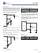
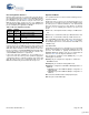
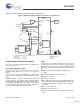
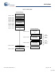
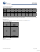
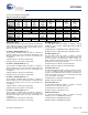
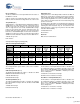
Table Of Contents
- EZ-Host Features
- Typical Applications
- Introduction
- Functional Overview
- Interface Descriptions
- USB Interface
- OTG Interface
- External Memory Interface
- General Purpose IO Interface (GPIO)
- UART Interface
- I2C EEPROM Interface
- Serial Peripheral Interface
- High-Speed Serial Interface
- Programmable Pulse/PWM Interface
- Host Port Interface
- IDE Interface
- Charge Pump Interface
- Booster Interface
- Crystal Interface
- Boot Configuration Interface
- Operational Modes
- Power Savings and Reset Description
- Memory Map
- Registers
- Processor Control Registers
- CPU Flags Register [0xC000] [R]
- Bank Register [0xC002] [R/W]
- Hardware Revision Register [0xC004] [R]
- CPU Speed Register [0xC008] [R/W]
- Power Control Register [0xC00A] [R/W]
- Interrupt Enable Register [0xC00E] [R/W]
- Breakpoint Register [0xC014] [R/W]
- USB Diagnostic Register [0xC03C] [R/W]
- Memory Diagnostic Register [0xC03E] [W]
- External Memory Registers
- Timer Registers
- General USB Registers
- USB Host Only Registers
- Host n Control Register [R/W]
- Host n Address Register [R/W]
- Host n Count Register [R/W]
- Host n Endpoint Status Register [R]
- Host n PID Register [W]
- Host n Count Result Register [R]
- Host n Device Address Register [W]
- Host n Interrupt Enable Register [R/W]
- Host n Status Register [R/W]
- Host n SOF/EOP Count Register [R/W]
- Host n SOF/EOP Counter Register [R]
- Host n Frame Register [R]
- USB Device Only Registers
- Device n Endpoint n Control Register [R/W]
- Device n Endpoint n Address Register [R/W]
- Device n Endpoint n Count Register [R/W]
- Device n Endpoint n Status Register [R/W]
- Device n Endpoint n Count Result Register [R/W]
- Device n Port Select Register [R/W]
- Device n Interrupt Enable Register [R/W]
- Device n Address Register [W]
- Device n Status Register [R/W]
- Device n Frame Number Register [R]
- Device n SOF/EOP Count Register [W]
- OTG Control Registers
- GPIO Registers
- IDE Registers
- HSS Registers
- HSS Control Register [0xC070] [R/W]
- HSS Baud Rate Register [0xC072] [R/W]
- HSS Transmit Gap Register [0xC074] [R/W]
- HSS Data Register [0xC076] [R/W]
- HSS Receive Address Register [0xC078] [R/W]
- HSS Receive Counter Register [0xC07A] [R/W]
- HSS Transmit Address Register [0xC07C] [R/W]
- HSS Transmit Counter Register [0xC07E] [R/W]
- HPI Registers
- SPI Registers
- SPI Configuration Register [0xC0C8] [R/W]
- SPI Control Register [0xC0CA] [R/W]
- SPI Interrupt Enable Register [0xC0CC] [R/W]
- SPI Status Register [0xC0CE] [R]
- SPI Interrupt Clear Register [0xC0D0] [W]
- SPI CRC Control Register [0xC0D2] [R/W]
- SPI CRC Value Register [0xC0D4] [R/W]
- SPI Data Register [0xC0D6] [R/W]
- SPI Transmit Address Register [0xC0D8] [R/W]
- SPI Transmit Count Register [0xC0DA] [R/W]
- SPI Receive Address Register [0xC0DC [R/W]
- SPI Receive Count Register [0xC0DE] [R/W]
- UART Registers
- PWM Registers
- Processor Control Registers
- Pin Diagram
- Pin Descriptions
- Absolute Maximum Ratings
- Operating Conditions
- Crystal Requirements (XTALIN, XTALOUT)
- DC Characteristics
- AC Timing Characteristics
- Register Summary
- Ordering Information
- Package Diagrams
- Document History Page
- Sales, Solutions, and Legal Information
CY7C67300
Document #: 38-08015 Rev. *J Page 11 of 99
Booster Interface
EZ-Host has an on chip power booster circuit for use with power
supplies that range between 2.7V and 3.6V. The booster circuit
boosts the power to 3.3V nominal to supply power for the entire
chip. The booster circuit requires an external inductor, diode, and
capacitor. During power down mode, the circuit is disabled to
save power. Figure 6 shows how to connect the booster circuit.
Component details:
■ L1: Inductor with inductance of 10 µH and a current rating of at
least 250 mA
■ D1: Schottky diode with a current rating of at least 250 mA
■ C1: Tantalum or ceramic capacitor with a capacitance of at least
2.2 µF
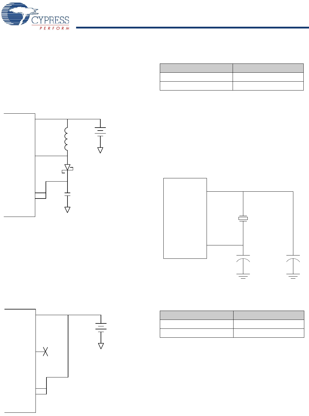
Figure 7 shows how to connect the power supply when the
booster circuit is not being used.
Booster Pins
Crystal Interface
The recommended crystal circuit to be used with EZ-Host is
shown in Figure 8 If an oscillator is used instead of a crystal
circuit, connect it to XTALIN and leave XTALOUT unconnected.
For further information about the crystal requirements, see Table
132, Crystal Requirements on page 83.
Noted that the CLKSEL pin (pin 38) is sampled after reset to
determine what crystal or clock source frequency is used. For
normal operation, 12 MHz is required so the CLKSEL pin must
have a 47K ohm pull up resistor to V
CC.
.
Crystal Pins
Figure 6. Power Supply Connection With Booster
Figure 7. Power Supply Connection Without Booster
BOOSTVcc
VSWITCH
VCC
AVCC
C1
D1
L1
3.3V
2.7V to 3.6V
Power Supply
BOOSTVcc
VSWITCH
VCC
AVCC
3.0V to 3.6V
Power Supply
Table 17. Charge Pump Interface Pins
Pin Name Pin Number
BOOSTVcc 16
VSWITCH 14
Figure 8. Crystal Interface
Table 18. Crystal Pins
Pin Name Pin Number
XTALIN 29
XTALOUT 28
Y1
C1 = 22 pF
C2 = 22 pF
CY7C67300
XTALIN
XTALOUT
12MHz
Parallel Resonant
Fundamental Mode
500uW
20-33pf ±5%
[+] Feedback