
Datasheet


MT-X1 Manual
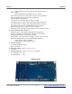
Port B All pins are routed to headers. The 1.25V precision reference can be connected
to pin B0 (Vref input) through a solder jumper. Note that JTAG is connected to
pins B4 – B7. JTAG must be disabled to use these pins for other purposes like
the ADC.
Port C All pins are routed to headers. No peripheral devices are connected to this port.
Port D All pins are routed to headers. This port also connects to the LEDs and 32KB
SPI SRAM memory through solder jumpers.
Port E All pins are routed to headers. This port also connects to the buttons and the
MicroSD card slot through solder jumpers.
Port F All pins are routed to headers. This port also connects to the USART of the USB
AVR (RX, TX, and optionally, XCK) as well as the SPI inputs of the relay driver
(MOSI and SCK) through solder jumpers. To minimize power consumption. TX
should be tristated before entering sleep.
Ports H, J, and K All pins are routed to headers. No peripheral devices are connected to these
ports. They can be used for GPIO or for use with external memory.
Pins Q0 and Q1 The 32.768KHz crystal is connected to these pins, which serve as the TOSC
input pins of the RTC.
Pins Q2 and Q3 Pin Q2 is routed to the chip select pin of the relay driver. Pin Q3 is routed to the
audio amplifier power-down pin. Neither pin is routed to a header.
Pins R0 and R1 Both of these pins are routed to an HC49 crystal footprint. A 22pF capacitor is
also connected to each line. Additionally, R1 can be connected to the USB AVR
8MHz clock output (CLKO) through solder jumper J7.
Buttons / Jumper
There are four modes of operation which are selected using the PROG button and JMP
jumper. The button and jumper are sampled when powering up or pressing reset. Additionally, the MT-
X1 can be switched between the AVRISP mkII programmer and the serial bridge during runtime by
pressing the PROG button. This is useful, for example, to program the XMEGA, then switch to the
serial bridge for printf() debugging. The reset button resets the USB AVR, which will in turn reset the
XMEGA when it boots. The following table lists the mode selection during power-up and reset.
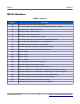
Mode Selection During Power-up and Reset
PROG Button JMP Jumper Mode
Pressed Installed DFU Bootloader
Not Pressed Installed Configuration Mode
Pressed Not Installed AVRISP mkII PDI Programmer
Not Pressed Not Installed USB Serial Bridge
January 29, 2015 8 http://www.mattairtech.com/