MTX1 January 29, 2015 Manual 1 http://www.mattairtech.
MTX1 Manual Table of Contents Overview........................................................................................................................3 Introduction....................................................................................................................................... 3 MTX1 Features................................................................................................................................ 3 ATxmega128a1 Features.................................
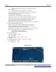
MTX1 Manual Overview Introduction The MTX1 is a flexible USB development board for the Atmel ATxmega128a1 microcontroller. Included is a MicroSD card slot, 32KB SPI SRAM, audio amplifier, lowside / relay driver, temperature sensor, 4 buttons, 4 LEDs, and an onboard 1.25V precision reference for the ADC. This reference is setup to work with the XMEGA errata. The XMEGA can be programmed over USB using the onboard AVRISP mkII compatible PDI programmer.
MTX1 ● ● ● ● ● ● ● ● ● ● ● ● ● ● ● ● Manual ● Can be used as generalpurpose lowside driver Audio amplifier connected to XMEGA DAC Temperature sensor with lowpower operation 1.25V precision voltage reference ● Works with XMEGA ADC errata ● Use for signed differential conversions from 0V to ~2.5V at the pin ● Routed to both reference inputs via solder jumpers 4 buttons 4 LEDs Available 1MB low power external SRAM (see http://www.mattairtech.
MTX1 ● ● ● ● Manual Advanced Waveform Extension on two Timer/Counters Eight USARTs IrDA modulation/demodulation for one USART Four 2Wire Interfaces w/ dual address match (I2C and SMBus) Four SPI (Serial Peripheral Interface) peripherals AES and DES Crypto Engine 16bit Real Time Counter with separate Oscillator Two Eightchannel, 12bit, 2 Msps Analog to Digital Converters Two Twochannel, 12bit, 1 Msps Digital to Analog Converters Four Analog Comparators with Window compare function External Interr
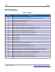
MTX1 Manual MTX1 Hardware Solder Jumpers Jumper Description J1 USB Shield to gnd (not connected by default) J2 ~5V to relay driver (5V header pin and kickback diodes common cathode) J3 DACA0 (pin A2) to amplifier audio input J4 AREF B (pin B0) to 1.25V reference J5 AREF A (pin A0) to 1.
MTX1 Manual Headers / Pin Descriptions Pin Description External Power Header Under the default configuration, 5V should be supplied to this pin. Lower voltages may be used down to around 4V (or lower if using less current). Voltages greater than 5.5V require J2 to be disconnected. Disconnecting J2 will disable the 5V output pin and inductive kickback protection of the relay driver. But it will allow voltages up to ~7.5V. This header is reverse polarity protected using a schottky diode. 3.
MTX1 Manual Port B All pins are routed to headers. The 1.25V precision reference can be connected to pin B0 (Vref input) through a solder jumper. Note that JTAG is connected to pins B4 – B7. JTAG must be disabled to use these pins for other purposes like the ADC. Port C All pins are routed to headers. No peripheral devices are connected to this port. Port D All pins are routed to headers. This port also connects to the LEDs and 32KB SPI SRAM memory through solder jumpers.
MTX1 Manual Power / Status LEDs There are two green LEDs that are used to indicate USB status, the mode of operation, communication activity, programmer status, and more. The following table lists LED functionality in each mode. Both LEDs are turned off in sleep mode.
MTX1 Manual prescalers can be used to obtain the various clocks. Be aware that the ATxmega128a1 requires both the 2MHz and 32MHz oscillators to be running and both DFLLs to be enabled for either DFLL to operate due to errata. Atmel ASF (Atmel Software Framework) does not support this arrangement, but the example code shows how to set this up. Also note that the DFLL calibrated oscillators will still not be as accurate as an external high speed crystal. If using an external crystal, it must be 0.
MTX1 Manual MicroSD Card The MicroSD card slot has a springloaded mechanism that locks the card in place when inserted (pushin, pushout). The contacts are goldplated. It is connected to SPI E using four pins. All pins have external 47Kohm pullups installed, except for MISO, which requires the internal pullup to be enabled. All four pins can be disconnected from the MicroSD card slot using the solder jumpers.
MTX1 Manual Temperature Sensor The temperature sensor is the MCP9701ATE/TT from Microchip. It is connected to pin A1, and can be disconnected by using a solder jumper. It can sense from 10C to 125C, though the high temperature is limited to the maximum PCB temperature. It has an accuracy of +/ 2C (max.) and it outputs 19.5mV/C. It consumes only 6uA (typ.). For more information on this IC, please consult the datasheet.
MTX1 Manual Windows Installation Before plugging in the MTX1 for the first time, the latest software and drivers must be downloaded. The MTX1 is supported under Windows XP, Vista (32 and 64 bit), and Windows 7 (32 and 64 bit). There is limited support for Windows 2000. The MTX1 appears as three different devices to the PC depending on which mode is selected by the button and jumper.
MTX1 Manual Once Atmel Studio is installed, remove jumper JMP and plug in or reset the MTX1 while holding down the PROG button. This will run the AVRISP mkII compatible PDI programmer. LED_STS should be lit and LED_PWR should be PWM flashing on and off. You will then be prompted for the AVRISP mkII driver. By default, this is located in the Program Files/Atmel/AVR Jungo USB directory. Point the installer to the appropriate subdirectory for your PC architecture (usb32 or usb64) and install the driver.
MTX1 Manual MTX1 Driver / Serial Configuration Next, the MTX1 CDC driver can be installed, which is used by the serial bridge and configuration mode. This driver allows the board to appear as a COM port. The driver itself is included with Windows, but an .inf file is needed to configure it. Download the .inf file from https://www.mattairtech.com/software/MattairTech_CDC_Driver_Signed.zip. Note that Windows Vista 64bit, Windows 7 64bit and Windows 8 require the signed driver.
MTX1 Manual Linux Installation Linux is supported as well. You must download and build the toolchain from the latest script available at AVR Freaks on the AVR GCC Forum (Script for building AVR GCC sticky at http://www.avrfreaks.net/index.php?name=PNphpBB2&file=viewtopic&t=42631). All firmware written for the MTX1S is developed under Linux using this toolchain.
MTX1 Manual AVRISP mkII Compatible PDI Programmer The MTX1 onboard PDI Programmer is based on the AVRISP mkII compatible programmer written by Dean Camera (http://www.fourwalledcubicle.com/). AVR Studio 4.19, 5.x, Atmel Studio 6.x, and AVRDUDE are supported. Using Atmel Studio (AVR Studio) Start Atmel Studio and open or create a new project. An example project, which can be used as a template, is available for the MTX1 at http://www.mattairtech.com/software/MTX1/MT X1_Simple_Demo.zip.
MTX1 Manual Next, build the project. Then, click on the Device Programming button. In the Device Programming window, select the AVRISP mkII as the tool. If no tool appears, be sure that the MTX1 is plugged in and in programming mode (STS LED will be pulsing). Select the ATxmega128A1 as the device and PDI as the interface and click Apply. You should now be connected to the AVRISP mkII compatible programmer with serial number 000200012345. Now click Read next to Device signature.
MTX1 Manual Next, select the Memories page. In the Flash section, a hex file can programmed into the targets flash memory. Load your hex file, then click Program. The hex file for the MT X1_Simple_Demo is located in the Debug folder. You will need to erase the target first if you do not have “Erase Flash before programming” checked. You should also verify the flash as well. January 29, 2015 19 http://www.mattairtech.
MTX1 Manual Next, select the Fuses page. It is best to leave the fuse settings alone until you understand what they do. In particular, do not set the BOD (Brownout detection) voltage too close to 3.3V, as this could cause the target to be held perpetually in reset. Due to errata, the BOD should not be enabled in sampled mode when active or idle (BODACT). Sampled mode is OK for other sleep modes (BODPD). Now you may wish to look at the other pages.
MTX1 Manual Using AVRDUDE TODO (ie: avrdude p x128a1 c avrisp2 P usb U flash:w:"myfirmware.hex") January 29, 2015 21 http://www.mattairtech.
MTX1 Manual Serial Bridge The serial bridge can connect the XMEGA to a host application (ie: terminal emulator) over USB. The XMEGA simply uses one USART as it would with, for example, RS232. There is no need to learn the USB protocol or use a USB library. On the host side, the MTX1 will appear as a virtual COM port. Speeds of up to 2Mbps are supported. Configuration Before using the serial bridge, it must be configured to be compatible with the target. This configuration is stored in EEPROM.
MTX1 Manual Baud Rate Register Value (Manual Speed) Async 1X f osc −1 16∗BAUD UBRR= f osc 16∗UBRR1 BAUD= UBRR= BAUD= where Async 2X Synchronous f osc −1 8∗BAUD UBRR= f osc 8∗UBRR1 BAUD= f osc −1 2∗BAUD f osc 2∗UBRR1 f osc =8000000 January 29, 2015 23 http://www.mattairtech.
MTX1 Manual Configuration The MTX1 PDI programmer, serial bridge, and other features can be configured by entering configuration mode. This configuration is stored in nonvolatile EEPROM memory. Configuration mode requires an ANSI terminal emulator. Configuration options are highlighted by using the up and down arrow keys, and selected using the enter key. Some dialogs are for entering numbers in hexadecimal. Here, the left and right arrow keys and backspace are used.
MTX1 Manual XMEGA Demo Program Note: This page describes the preinstalled demo program. This program is primarily meant for testing. While the source code is available, it is not intended to be reused. The code is a collection of many code fragments. It is disorganized and complicated. It is recommended to use the Atmel Studio 6 ASF (Atmel Software Framework) template to get started (see Using Atmel Studio (AVR Studio)). The following relates to the preinstalled demo.
MTX1 Manual Firmware Updates The MTX1 firmware will be updated periodically to add new features and fix bugs. These updates will be available on the MattairTech website. The updates may include just a hex file (for programming flash), or both a hex file and eep file (for programming both flash and EEPROM). FLIP is a graphical utility for Windows used to load firmware updates onto the MTX1. FLIP includes the DFU bootloader driver. Download FLIP 3.4.2 or higher from http://www.atmel.com/tools/FLIP.
MTX1 Manual FLIP Plug in the MTX1 with jumper JMP installed and while holding down the PROG button. This will enter the DFU bootloader. LED_STS should be on and LED_PWR should be off. Now launch the FLIP utility. When it has loaded, click on the chip icon and select the AT90USB162. Next, click on the USB icon, select USB, then connect. The screen should now show information about the AT90USB162. Click on the File menu, and open the appropriate hex file. More information will appear about the program.
MTX1 Manual You may also need to program the EEPROM. If so, click on Select EEPROM at the bottom. Then, click on the File menu and open the appropriate eep file. You will have to change the file filter to allow you to see the eep file. Note that eep files are just hex files but with the eep extension instead of hex. More information will appear about the file when selected. Both Program and Verify should be checked. Click run to program the EEPROM. dfuprogrammer TODO Must erase chip first.
MTX1 Manual Troubleshooting / FAQ Nothing yet Support Information Please check the MattairTech website (http://www.MattairTech.com/) for firmware and software updates. Email me if you have any feature requests, suggestions, or if you have found a bug. If you need support, please contact me (email is best). You can also find support information at the MattairTech website. A support forum is planned. Support for AVRs in general can be found at AVRfreaks (http://www.avrfreaks.net/).
MTX1 Manual Schematic January 29, 2015 30 http://www.mattairtech.
MTX1 Manual Legal Notices Copyright Notices Copyright Copyright Copyright Copyright Copyright © © © © © 2009-2012, Justin Mattair (http://www.mattairtech.com/) 2009-2012, Dean Camera (http://www.lufa-lib.org) 2003-2012, Atmel Corporation (http://www.atmel.com/) 2009, CHaN (http://elm-chan.org/fsw/ff/00index_e.html) 2010, Peter Kwan (serial demo) Software Disclaimer The author(s) disclaim all warranties with regard to this software, including all implied warranties of merchantability and fitness.
MTX1 Manual Licenses LUFA USB Library Copyright 2012 Dean Camera (dean [at] fourwalledcubicle [dot] com) Permission to use, copy, modify, distribute, and sell this software and its documentation for any purpose is hereby granted without fee, provided that the above copyright notice appear in all copies and that both that the copyright notice and this permission notice and warranty disclaimer appear in supporting documentation, and that the name of the author not be used in advertising or publicity pert
MTX1 Manual Appendix A: Precautions CAUTION The MT-X1 contains static sensitive components. Use the usual ESD procedures when handling. CAUTION Improper fuse settings may result in an unusable AVR. Be certain that you know the effects of changing the fuses, that you understand the convention used for describing the state of the fuses (programmed = 0), and that you are using an appropriate programming speed before attempting to change fuse settings. January 29, 2015 33 http://www.mattairtech.