
Specifications


page
10
Access Method Devices Testing Method
I
2
C
CY22393 Clk, 9DB403 Clk Bfr, ADV7441A Digitizer, 3x CPLD, LM75, LM63
24LC256 EEPROM, ADS1015 4x ADC, MIPI Port, CX25858 EEPROM,
FX3 and CX3 Controllers, 9X130 PCI/PCIe Bridge, 24T6 PCIe Switch, E4690 Graphics
Verify and Initialize
Control Registers
UART Debug access to the FX3 and CX3 Controllers
Verify and Initialize
Control Registers
JTAG 3x CPLD, 9X130 PCI/PCIe Bridge, 24T6 PCIe Switch, E4690 Graphics ID and Boundary Test
HSYNC, VSYNC ADV7441A Digitizer, E4690 Graphics STM Counters
Voltage Power Supply: VDD_CORE, VDD_10, VDD_11, VDD_18, ancillary supplies STM A/D Inputs + ADS1015
Temperature STM on-chip sensor, LM63 and LM75 Thermal Sensors, E4690 Substrate Diode
poll via I
2
C registers
Table 4: AgatePXC BIST Test Nodes
Systems
Management
PPoowweerr
SSuuppppllyy
SSuubbssyysstteemm
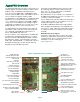
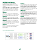
By the very definition of a high-performance graphics
board, the Agate is NOT a low-power design. For it to
meet its full design specification, the calculated power
requirements are:
Host Bus Voltage Input Idle Full Operation
PMC/XMC 3.3V 0.9A 2A
PMC 5V 2.45A 6.85A
XMC VPWR=5V 2.45A 6.85A
VPWR=12V 1.1A 3A
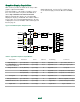
At the leading edge of system reset, logic selects PMC or
XMC as the power source (XMC is default). Because it
can deliver the most power, 5V is the power rail for the 4-
phase quad DC-DC converter supply. When XMC
VPWR=12V, a local DC-DC converter is enabled to down-
convert it to 5V. There is small efficiency cost to doing this
but it simplifies the overall design. An OVP shuts down the
entire power section if local 5V exceeds 5.6V.
TTeemmppeerraattuurree
MMoonniittoorriinngg
SSuubbssyysstteemm
An LM63 thermal sensor tied to an E4690 substrate diode
monitors the E4690 and the area around it. An LM75 sen-
sor monitors the DC-DC converters area. If a thermal con-
dition is detected, an LED is lit and, if required, the board
is shut down. Recovery is done by cycling system power.
CCoooolliinngg
SSyysstteemmss
Copper floods enhance the heat-spreading within the
PCB. The 24T6 and E4690 PCIe bus widths (set on-board
to x4 or x8) and the E4690 clock and core voltage also
affect power dissipation. The BIST subsystem can adjust
the GPU parameters when temperatures rise too high.
This may be a more effective way to manage heat than
adding a heat sink that may congest the air flow through
the cardcage. Tests will have to be run in the customer
system to determine the impact.
BBuuiilltt-IInn
SSeellff-TTeesstt
((BBIISSTT))
CCoonnttrrool
llleerr
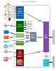
An ST Micro STM32F427 CPU is used to provide Built-In
Self-Test (BIST) and real-time monitoring of many
AgatePXC functions using a combination of
I
2
C, JTAG,
and A to D converters (ADC) for voltage measurements.
The STM firmware includes support for boot-time register
setup, device testing, and even CPLD reprogramming.
The STM is connected to one of the uPD720201 USB
ports so that it can be controlled by the host system.
EErrrroorr
RReeppoorrttiinngg
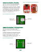
The simplest way that problems are reported is by LEDs:
On the front panel are:
Red “Err” LED, which is turned on if a thermal sensor is
tripped or some other problem is detected;
Green “ST” LED driven by the STM, slowly cycles on and off.
Green “VOK” LED, which is turned on when all on-board
supplies are normal;
Amber “CX” LED driven by the CX3, slowly cycles on and off.
On Side 2, along the board edge,
Green, Amber, and Red LEDs driven by [STM OR 24T6 OR
CPLD] control bits.
Amber LED driven by the FX3, slowly cycles on and off.
In addition to the LEDs, the STM can communicate with
the host system via an Agate USB port. No cabling to an
CPU port is required.
SSyysstteemm
MMaannaaggeemmeenntt
CCoonnnneeccttiioonnss
A Mini B USB connector located on the edge of the board
enables access to the STM secondary USB port for use
with USB peripheral devices.
A Micro AB USB connector is used as for debug but is
NOT a USB port. It is used to support programming of the
STM control store and to access the STM debug port.
There are a number of subsystems on the AgatePXC that
are required to enable its correct and reliable operation.
The startup of the power systems is set in motion by the
leading edge of the system reset pulse. All host power
must be stable at that time in order to ensure the proper
operation of the board.