
User guide


52 Document No. 001-64846 Rev. *A Getting Started with CapSense®
3.7.10 Vias
Use the minimum number of vias to route CapSense inputs to minimize parasitic capacitance. The via should be
placed to minimize the trace length, which is usually on the edge of the sensor pad, as shown in Figure 3-33.
Figure 3-33. Via Placement on Sensor Pad
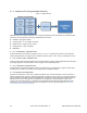
3.7.11 Ground Plane
Ground fill is added to both the top and bottom of the sensing board. When ground fill is added near a CapSense
sensor pad, there is a tradeoff between maintaining a high level of CapSense signal and increasing the noise
immunity of the system. Typical hatching for the ground fill is 15 percent on the top layer (7 mil line, 45 mil spacing)
and 10 percent on the bottom layer (7 mil line, 70 mil spacing).
Figure 3-34. Recommended Button and Slider Layout Top Layer