
User guide


Getting Started with CapSense Document No. 001-64846 Rev. *A 51
3.7.9 Crosstalk Solutions
A common backlighting technique for panels is to mount an LED under the sensor pad so that it shines through a
hole in the middle of the sensor. When the LED is switched on or off, the voltage transitions on the trace that drives
the LED can couple into the capacitive sensor input, creating noisy sensor data. This coupling is referred to as
crosstalk. To prevent crosstalk CapSense and non-CapSense traces should be isolated from one another. A
minimum separation of 4 mm is recommended. A hatched ground plane also can be placed between those traces to
isolate them. LED drive traces and CapSense traces should not be routed together.
Figure 3-30. NOT Recommended - LED and CapSense in Close Proximity
Figure 3-31. Recommended - LED and CapSense with Wide Separation
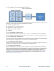
Another approach to reducing crosstalk is to slow down the rising and falling edges of the LED drive voltage using a
filter capacitor. Figure 3-32 shows an example circuit of this solution. The value of the added capacitor depends on
the drive current requirements of the LED; however, a value of 0.1 µF is typical.
Figure 3-32 Filter Capacitor Solution for Crosstalk
VDD
LED
CapSense
Sensor
Capacitor
Series
resistor
CapSense
Controller
LED
Port Pin
Sensor
Port Pin