
User guide


Getting Started with CapSense Document No. 001-64846 Rev. *A 47
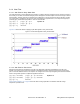
Figure 3-24. NOT Recommended: Port Isolation for Communication, CapSense, and LEDs
CapSense Controller
VDDVDD
PWM or other
Non-CapSense traces
Communication
traces
X X
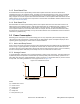
In Figure 3-25, good isolation is achieved, but note that the LEDs are placed next to the ground pin. The CapSense
sensors are assigned to edge of the chip that does not include ground. Minimizing the distance between CapSense
pins and the ground pin will lead to lower parasitic capacitance for the traces. This is also an example of a bad pin
assignment.
Figure 3-25. NOT Recommended: Port Isolation for Communication, CapSense and LEDs
CapSense Controller
VDD
PWM or other
Non-CapSense traces
Communication
traces
X X