
User guide


46 Document No. 001-64846 Rev. *A Getting Started with CapSense®
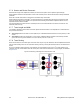
3.6 Pin Assignments
An effective method to reduce interaction between CapSense sensor traces and communication and non-CapSense
traces is to isolate each by port assignment. Figure 3-23 shows a basic version of this isolation for a 32-pin QFN
package. Because each function is isolated, the CapSense controller is oriented such that there is no crossing of
communication, LED, and sensing traces.
Figure 3-23. Recommended: Port Isolation for Communication, CapSense, and LEDs
The CapSense controller architecture imposes a restriction on current budget for even and odd port pin numbers. For
a CapSense controller, if current budget of odd port pin is 100 mA, total current drawn though all odd port pins should
not exceed 100 mA. In addition to the total current budget limitation, there is also maximum current limitation for each
port pin. Refer to the datasheet of the CapSense controller used in the application to know the specification of that
particular CapSense controller.
All CapSense controllers provide high current sink and source capable port pins. When using high current sink or
source from port pins, select the ports that are closest to device ground pin to minimize the noise.
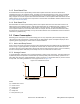
The following two examples demonstrate common pin assignment mistakes. In Figure 3-24 on page 47, CapSense
and non-CapSense traces are not isolated, and CapSense pins are far from ground. This is an example of a bad pin
assignment.