
User guide


Getting Started with CapSense Document No. 001-64846 Rev. *A 29
3. Design Considerations
When designing capacitive touch sense technology into your application it is crucial to keep in mind that the
CapSense device exists within a larger framework. Careful attention to every level of detail from PCB layout to user
interface to end-use operating environment leads to robust and reliable system performance.
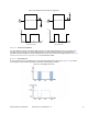
3.1 Overlay Selection
In a CapSense design, overlay material is placed over the sensor pad to protect it from the environment and prevent
direct finger contact.
3.1.1 Relationship to CapSense Signal Strength
In the Self-Capacitance Equivalent Model section, Equation 1 was presented for finger capacitance.
=
Where:
ε
0
ε
= Free space permittivity
r
A = Area of finger and sensor pad overlap
= Dielectric constant of overlay
D = Overlay thickness
To increase the CapSense signal, choose an overlay material with higher dielectric constant, decrease the overlay
thickness, and increase the button diameter.
Table 3-1. Overlay Material Dielectric Strength
Material Breakdown Voltage (V/mm) Min. Overlay Thickness at 12 kV (mm)
Air 1200–2800 10
Wood – dry 3900 3
Glass – common 7900 1.5
Glass – Borosilicate (Pyrex
®
13,000 ) 0.9
PMMA Plastic (Plexiglas
®
13,000 ) 0.9
ABS 16,000 0.8
Polycarbonate (Lexan
®
16,000 ) 0.8
Formica 18,000 0.7
FR-4 28,000 0.4
PET Film (Mylar
®
280,000 ) 0.04
Polymide film (Kapton
®
290,000 ) 0.04
Conductive material cannot be used as an overlay because it interferes with the electric field pattern. For this reason,
do not use paints that contain metal particles in the overlay.