
User guide


Getting Started with CapSense Document No. 001-64846 Rev. *A 27
2.8 CapSense System Overview
CapSense solutions include not only the CapSense devices, but the entire environment in which they operate.
2.8.1 Hardware Component
The CapSense controller resides within a larger system composed of a specially printed circuit board (PCB), and a
touch-surface called the overlay that protects the PCB.
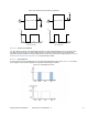
Figure 2-30. Exploded View of the CapSense Hardware
The capacitive sensor pads of a sensor board are formed by the PCB traces. The most common PCB format is a two-
layer board with sensor pads and a hatched ground plane on the top, and the electrical components on the bottom.
The electrical components include the CapSense controller and associated parts that convert the sensor capacitance
into digital counts. A cross-sectional view of a two-layer board stack-up is shown in Figure 2-31.
Figure 2-31. Two-Layer Stack Up of a CapSense Board
Four-layer designs are an option when board area must be minimized. PCB layout plays a very important role in
CapSense system performance. Best practices are discussed in Design Considerations.
2.8.2 Firmware Component
Firmware is a vital component of the CapSense system that processes the raw count data and makes logical
decisions. The amount of firmware development required for your application depends on which CapSense device
you select.