
User guide


Getting Started with CapSense Document No. 001-64846 Rev. *A 25
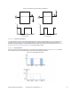
Figure 2-29. PWM Clock Divider Calculation
To calculate the clock dividers to obtain a 2.4-kHz PWM output, see Figure 2-29. The System clock is set to 24 MHz.
The required PWM output frequency is 2.4 kHz. Hence,
/ (1 2 ( + 1) ) = 2.4 Equation 7
Where, N1 and N2 are the VC1 and VC2 clock divider values respectively. Period Value is the value of period register
input to the PWM.
That means:
24 /(1 2 ( + 1) ) = 2.4 Equation 8
Rearranging the equation we get:
1 2
(
+ 1
)
= 10000 Equation 9
The above equation has various integral solutions. For simplicity, this example will use N1 = 4 and N2 = 10.
Substituting these values in the above equation we get
+ 1 = 10000
(
4 10
)
250 Equation 10
Thus, Period Value is 249. To have a 50-percent duty cycle, the Compare value for the PWM is set as
(
+ 1
)
2
=
(
249 + 1
)
2 125
Equation 11
User Module parameters are matched as shown in the following table.
Table 2-1. PWM8 User Module Parameters
Parameter Value
Name PWM
Configuration 8 bit
Clock VC2
Period 249
Pulse Width 125
Compare Type Less than
Interrupt Type Compare True
Clock Sync Sync to SysClk
Note that the CSD user module automatically varies the clock dividers based on scan speed and resolution settings
of the CSD user module. Therefore, re-enter the clock dividers every time the PWM module is invoked by writing the
values directly to the configuration register OSC_CR1.The details about the Configuration register OSC_CR1 is
present in the Technical Reference Manual.
The clock dividers VC1, VC2, and VC3 vary with the CSD scan speed and resolution as shown in Table 2-2 and
Table 2-3 on page 26.