
User guide


20 Document No. 001-64846 Rev. *A Getting Started with CapSense®
Features of a design based on springs/gaskets/foam:
Electrical field coupled from PCB to overlay using a compressed spring, or conductive gasket or foam
Conductive material itself acts as capacitive sensor pad
No mechanical moving parts. Springs and foam do not move
Coupled to touch sensor surface via nonconductive overlay
Any conductive overlay serves as the button touch surface
Ideal topology for curved, sloping or otherwise irregular front panels
Ideal for designs where touch sensor surface is physically separated from silicon or mother board
Ideal for designs where CapSense and mechanical button combination is desired
2.6.3 Field Coupled via Printed Ink
Features of a design based on printed ink:
Electric field coupled with printed patterns on a flexible substrate using conductive ink
High series resistance due to higher ohms-per-square of printed ink compared to copper
High parasitic capacitance due to thin PCB
No mechanical moving parts, but substrate is flexible
Coupled to touch sensor surface with a nonconductive overlay
Ideal topology for flexible front panels
Flexible PCB can be one-layer or two-layer film
2.6.4 Field Coupled via ITO Film on Glass
Features of a design based on ITO film:
Electric field coupled with printed or deposited patterns on glass
Higher series resistance of ITO films compared to copper and printed ink
No mechanical moving parts
Ideal topology for graphical front panels
2.7 CapSense Feedback
Effective user interface designs include some type of feedback to the user when they are using the capacitive touch
sense buttons. There are various forms of feedback, including visual, audio, and haptic (tactile). Depending on the
user interface design multiple types of feedback can be used in combination.
2.7.1 Visual Feedback
LEDs and LCDs provide visual feedback to the user.
2.7.1.1 LED-based Visual Feedback
LEDs are used to indicate the status of buttons, sliders, and proximity sensors. LEDs can implement different effects
when the sensor status changes.
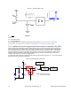
2.7.1.1.1 LED ON/OFF
In visual feedback’s simplest form, LEDs are turned ON or OFF in response to a finger touch. General-purpose I/Os
are used to drive LEDs in either a sourcing or sinking configuration, as shown in Figure 2-20 on page 21.