
User guide


Getting Started with CapSense Document No. 001-64846 Rev. *A 17
2.5.2.1 Linear Sliders
In a linear slider each CapSense controller I/O pin is connected to one slider segment. A zigzag pattern (double
chevron) is recommended for slider segments. This layout ensures that when a segment is touched, the adjacent
segments are also partially touched. Sensor data from multiple sensors improves the estimate of the finger position.
The maximum number of slider segments is a function of the number of available CapSense controller pins and the
required response time.
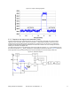
Figure 2-14. Linear Slider
0 1 2
3 4 5 6 7
0
1
2
3
4
5
6
7
Raw Counts
CapSense
Controller
Area contacted by finger
2.5.2.2 Diplexed Sliders
In a diplexed slider each CapSense controller I/O pin is connected to two different slider segments. This allows a
design to have twice as many slider segments as there are I/O pins. For example, a diplexed 16-segment slider
requires only eight CapSense controller I/O pins.
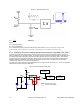
Figure 2-15. 16-Segment Diplexed Slider
0 1 2
3 4 5 6 7 0 3 6 1 4 7 2 5
0
1
2
3
4
5
6
7
0
3
6
1
4
7
2
5
Adjacent Sensor Actuation
Scattered Actuation
CapSense
Controller
Area contacted by finger
For a diplexed slider to work properly the slider segments must be connected to the CapSense controller I/O pins in a
pre-determined order. The first half of the segments are connected to the CapSense controller I/O pins sequentially
(0, 1, 2 …7) and operate just like a linear slider. The second half of the segments are connected to the same
CapSense controller I/O pins in a non-sequential order. This order exploits the fact that activation of one segment
results in partial actuation of neighboring segments. While slider actuation of one half of the slider will result in
aliasing onto the other half, the levels will be scattered in the untouched half. Sensing algorithms search for strong
adjacent segment actuation and ignore scattered actuation in order to accurately determine finger position on the
slider.