
User`s guide


Quad Independent Channel
HOTLink II™ CYV15G0404DXB
Video PHY Demonstration Board
Page 26 of 92
15.View the picture display of the signal on the WFM 700. The user should see the EG1 color bars in SD-SDI format displayed.
16.Press the “Stop” button for all channels.
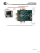
Note: For this test, the clock headers for channel A can be configured to either the on-board programmable clock option or the
on-board 74.25-MHz crystal oscillator clock option. Clock headers for channel B and channel D should be configured to the on-
board programmable clock option.
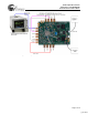
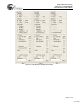
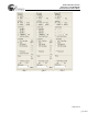
Figure 6-10. Sample Test 4–Selectable Inputs and Auto Rate Detection
[+] Feedback