EZ-USB Development Kit Manual Getting Started Rev 1.
Cypress Disclaimer Agreement The information in this document is subject to change without notice and should not be construed as a commitment by Cypress Semiconductor Corporation Incorporated. While reasonable precautions have been taken, Cypress Semiconductor Corporation assumes no responsibility for any errors that may appear in this document. No part of this document may be copied or reproduced in any form or by any means without the prior written consent of Cypress Semiconductor Corporation.
Table of Contents EZ-USB Development Kit Overview . . . . . . . . . . . . . . . . . . . . . . . . . . . . . . . . . . . . . . . . . . . . . . . .1 Introduction . . . . . . . . . . . . . . . . . . . . . . . . . . . . . . . . . . . . . . . . . . . . . . . . . . . . . . . . . . . . . . . .1 EZ-USB Development Kit Contents . . . . . . . . . . . . . . . . . . . . . . . . . . . . . . . . . . . . . . . . . . . . .1 Required Tools Not Included. . . . . . . . . . . . . . . . . . . . . . . . . . . . . . . . . . . . .
ii Table of Contents
Getting Started 1.0 EZ-USB Development Kit Overview 1.1 Introduction The EZ-USB Development Kit (DVK) is the best starting point for developing an EZ-USB based product. The DVK includes everything you will need to get started: A development board, example firmware, a generic device driver, documentation, and assorted tools. This manual provides a general overview and installation guide for the DVK.
EZ-USB Development Kit Manual - Getting Started • Cypress USB Console • Cypress GPIF Designer • Cypress Firmware Download Driver sample • EZ-USB Documentation and Help Files • Reference Schematics • Limited Evaluation Version of the Keil 8051 Development Tools (Compiler, Assembler, IDE, Debugger) 1.2.
2.2 Compatibility with Earlier EZ-USB Development Kits This EZ-USB Advanced DVK has the ability to co-exist with older EZ-USB Development Kits. This DVK uses the same basic directory structure as the older Development Kits. The only conflict with older development kits is with driver binding. The older DVK used a different device driver - the EZ-USB General Purpose Driver. That device driver is bound to the VID/PID of the EZ-USB FX2 chip: VID=0x04B4 and PID=0x8613. The EZ-USB FX2LP shares the same PID.
EZ-USB Development Kit Manual - Getting Started • Windows 98 and 98SE – For PCI add-in adapters, drivers may be available from the adapter's manufacturer. However, these versions of Windows are not supported by the EZ-USB DVK. You can verify that high-speed drivers are installed and correctly bound to your host controller by looking under Device Manager. To open the device manager, run devmgmt.msc which is located in the Windows System32 Directory.
3.1 Confirm Successful Installation using the Cypress USB Console Run the Cypress USB Console application and perform a "Get Device Descriptor" operation. The Console is added to the Windows Start menu by the DVK Setup program under: Start->Cypress->USB->CyConsole – EZ-USB mode This link starts the USB Console in EZ-USB mode. After starting the USB Console, click on the “GetDev” button to retrieve the Device Descriptor from your Development Board.
EZ-USB Development Kit Manual - Getting Started 4.0 EZ-USB Advanced Development Board 4.1 Introduction The Cypress Semiconductor EZ-USB Advanced Development Board provides a compact evaluation and design vehicle for the EZ-USB family. The board provides expansion and interface signals on six 20-pin headers. A mating prototype board allows quick construction and testing of USB designs. All ICs on the board operate at 3.3 volts. The board may be powered from the USB connector or an external power supply.
4.3 Jumpers Table 1. EZ-USB Development Board Jumpers Jumper Function Default Notes JP1 Connects 3.3 volt power to the EZ-USB chip. IN (1-2) JP2 Powers the on-board 3.3 volt regulator from USB Vbus pin IN (1-2) To operate the board in self-powered mode, remove JP2 and supply 4-5V to JP2-1, and GND to a ground pin (TP1 is a convenient GND point).
EZ-USB Development Kit Manual - Getting Started Table 2. Typical EZ-USB external EEPROMS EEPROM Type Size A2A1A0 Typical P/N “Small” 16x8 000 24LC00 128x8 000 24LC01 256x8 000 24LC02 8Kx8 001 24LC64/5 “Large” “Small” EEPROMS are typically used to supply custom VID and PID information, allowing the EZUSB to enumerate with a driver associated with your EZ-USB design.
3. ‘C2 Load’: SW2=ON, SW1=LARGE A “C2” load provides a method for loading the EZ-USB internal RAM with 8051 firmware before enumeration. This ‘boot load’ mechanism allows EZ-USB to enumerate as a fully custom device, since the 8051 code handles enumeration using VID/PID values embedded in the code. At power-on, if the EZ-USB chip detects an EEPROM with the hex value ‘C2’ as its first byte, it continues to load an EZ-USB configuration byte, followed by blocks of 8051 code.
EZ-USB Development Kit Manual - Getting Started • High speed EZ-USB strobe signals (PSEN, WR#, CLKOUT, IFCLK, and RD#) are connected to pin 3 of each of the five connectors P1-P6, so that they may be used as the logic analyzer clock CLK1. • CLK2 is not used. Instead, each connector brings 3.3V power from the EZ-USB Development Board up to the prototype board using pin 2. • The signals are logically grouped.
Table 6. Alternate Default P3 Default N.C. 1 2 3.3V WR# 3 4 RDY5 RDY4 5 6 RDY3 RDY2 7 8 BKPT Alternate RESET# 9 10 N.C. N.C. 11 12 PC7 GPIFADR7 GPIFADR6 PC6 13 14 PC5 GPIFADR5 GPIFADR4 PC4 15 16 PC3 GPIFADR3 GPIFADR2 PC2 17 18 PC1 GPIFADR1 GPIFADR0 PC0 19 20 GND Table 7. Alternate Default P4 Default N.C. 1 2 3.3V CLKOUT 3 4 GND OE# 5 6 CS# 5V 7 8 5V PLD2 9 10 PLD1 N.C.
EZ-USB Development Kit Manual - Getting Started Table 9. Alternate Default P6 Default N.C. 1 2 3.3V RD# 3 4 INT5# INT4 5 6 T2 T1 7 8 T0 WAKEUP# 9 10 SDA Alternate SCL 11 12 PE7 GPIFADR8 T2EX PE6 13 14 PE5 INT6 RxD1OUT PE4 15 16 PE3 RxD0OUT T2OUT PE2 17 18 PE1 T1OUT T0OUT PE0 19 20 GND 4.6 ATA Connector P8 Table 10 shows the pinout for P8, a 40-pin connector that interfaces with a standard ATA cable. Note: This is for ATA use only.
4.7 U2 -- 22v10 GAL A standard 22v10 GAL provides general purpose “glue logic” on the board. It provides the AND gate required to combine the PSEN and READ signals, adds memory map support, debug LEDs and provides three spare outputs for customer defined functions. 4.
EZ-USB Development Kit Manual - Getting Started – The third column, “Ext Flash”, allows a flash memory (or other ROM) to be connected to the 8051 bus. This is the only configuration that starts 8051 execution from external memory (the GAL sets EA=1). Since external memory occupies the bottom 16K, the internal EZ-USB RAM is addressed only as data memory, instead of combined prog/data memory in the other three configurations. – The fourth column, “Single Chip”, disables all external memory.
Bit Switch 0 S2 1 S3 2 S4 3 S5 U9 has the group address 0100, and is strapped to unit address 000. Therefore to read the switch values, 8051 firmware sends a control byte of 01000001 (the LSB indicates a read operation), and then reads the data byte. 4.10 Indicators—Power and Breakpoint LED D1 is connected to the PCB 5 volt supply, which is normally supplied from the USB cable (VBUS pin). Alternatively, JP2 may be removed and external 5 volt power can be applied to JP2 pin 1.
EZ-USB Development Kit Manual - Getting Started These 4 jumpers must be in place D5 D4 Indicator D3 D2 Turn ON by reading Turn OFF by reading D2 0x88-- 0x80-- D3 0x98-- 0x90-- D4 0xA8-- 0xA0-- D5 0xB8-- 0xB0-- The low address byte is “don’t care”.
5.0 Frequently Asked Questions Q1: What should I do first (after viewing the printed material from the box)? A1: Make sure the hardware works well enough to run the Tutorial. After software installation, plug in a Dev Board, and go through the DVK tutorial. The tutorial is located in the “EZ-USB DVK User’s Guide“ which can be found in the “Start“ menu under Cypress >usb >help. The tutorial is short and worthwhile.
EZ-USB Development Kit Manual - Getting Started Q10: Where can I get a summary of the registers? A10: See the register summary in the TRM. Q11: Are there any examples? A11: Yes, see the examples and readme files in the Examples folder. Q12: What's all this set environment stuff? A12: If you install into the default directory, "C:\CYPRESS\USB" then you can build and debug examples with the Keil uV2 project files provided.
6.0 Appendix A: U2 (GAL) code (file is 'FX2LP.ABL') MODULE fx2lp " Swapped dipswitch settings 00 and 10 on 4-3-98 to allow the all-switchon default x,c,z = .X.,.C.,.Z.
EZ-USB Development Kit Manual - Getting Started !nRAMOE= !nRD # !nPSEN; EA = 0; } ELSE WHEN(modesw == 10) THEN" All program mem external { !nRAMCE = 1; !nRAMOE =!nRD # !nPSEN; EA = 1; } test_vectors ([mm1,mm0,A15,nRD,nPSEN] -> [nRAMCE, nRAMOE, EA]) [ 0 , 0 , x , x , x ] -> [ 1 , 1 , 0];" 10: all mem selects and strobes OFF [ 0 psen [ 0 [ 0 [ 0 , 1 , 0 , 1 , 1 ] -> [ 1 , 1 , 0];" 01: top of mem for rd or , 1 , 1 , 1 , , 1 , 1 , 0 , , 1 , 1 , 1 , 0 1 1 ] -> [ 0 ] -> [ 0 ] -> [ 0 , , , 0 , 0 , 1 ,
Figure 1-2.
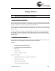
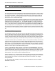
EZ-USB Development Kit Manual - Getting Started The schematic for the CY3684 appears on the following page. Page -22 EZ-USB Development Kit Manual - Getting Started Rev 1.
A B C D 3216 10 uFd 16v C25 C21 1M + 5V 5 9 4 8 3 7 2 6 1 P10 SIO-1 5 9 4 8 3 7 2 6 1 1 2 3 4 5 6 FRAME 1A 2A 3 0805 nSHDN IN FRAME S6 1B 2B C39 3216 C41 5 0.1 uFd TP7 3.3V WAKEUP# 100K R28 0805 0805 2 7 8 14 13 5 4 3.3V C1- C1+ V- 0.1 uFd C42 TXD1 RXD1 0.1 uFd C40 10 9 6 D7 0805 390 R15 R21 R23 SCL SDA 1 2 3 13 14 15 3.
EZ-USB Development Kit Manual - Getting Started Page -24 EZ-USB Development Kit Manual - Getting Started Rev 1.