
Datasheet


Migrating from EZ-USB
®
FX2LP™ Based Design to EZ-USB FX3 Based Design
www.cypress.com Document No. 001-76348 Rev. ** 9
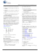
/* Consumer endpoint configuration */
apiRetStatus =
CyU3PSetEpConfig(CY_FX_EP_CONSUMER,
&epCfg);
if (apiRetStatus != CY_U3P_SUCCESS)
{
CyU3PDebugPrint (4,
"CyU3PSetEpConfig failed, Error code =
%d\n", apiRetStatus);
CyFxAppErrorHandler (apiRetStatus);
}
/* Create a DMA Auto Channel between two
sockets of the U port.
* DMA size is set based on the USB speed.
*/
dmaCfg.size = size;
dmaCfg.count =
CY_FX_BULKLP_DMA_BUF_COUNT;
dmaCfg.prodSckId =
CY_FX_EP_PRODUCER_SOCKET;
dmaCfg.consSckId =
CY_FX_EP_CONSUMER_SOCKET;
dmaCfg.dmaMode = CY_U3P_DMA_MODE_BYTE;
dmaCfg.notification = 0;
dmaCfg.cb = NULL;
/*In case if we are going to use DMA Manual
then we need assign a call back function to
dmaCfg.cb. (dmaCfg.cb =
CyFxBulkLpDmaCallback;)
dmaCfg.prodHeader = 0;
dmaCfg.prodFooter = 0;
dmaCfg.consHeader = 0;
dmaCfg.prodAvailCount = 0;
apiRetStatus = CyU3PDmaChannelCreate
(&glChHandleBulkLp,
CY_U3P_DMA_TYPE_AUTO, &dmaCfg);
if (apiRetStatus != CY_U3P_SUCCESS)
{
CyU3PDebugPrint (4,
"CyU3PDmaChannelCreate failed, Error code =
%d\n", apiRetStatus);
CyFxAppErrorHandler(apiRetStatus);
}
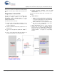
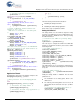
Application Thread
The Application entry point for the bulkloop example is the
BulkLpAppThread_Entry () function.
/* Entry function for the BulkLpAppThread.
*/
void
BulkLpAppThread_Entry (uint32_t input)
{
/* Initialize the debug module */
CyFxBulkLpApplnDebugInit();
/* Initialize the bulk loop application */
CyFxBulkLpApplnInit();
for (;;)
{
CyU3PThreadSleep (1000);
}
}
The main actions performed in this thread are:
Initializing the debug mechanism
Initializing the main bulkloop application
Each of these steps is explained as follows.
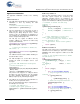
Debug Initialization
The debug module uses the UART to output the debug
messages. The UART has to be first configured before the
debug mechanism is initialized. This is done by invoking
the UART init function.
/* Initialize the UART for printing debug
messages */
apiRetStatus = CyU3PUartInit();
The next step is to configure the UART. The UART data
structure is first filled in and this is passed to the UART
SetConfig function.
/* Set UART Configuration */
uartConfig.baudRate =
CY_U3P_UART_BAUDRATE_115200;
uartConfig.stopBit =
CY_U3P_UART_ONE_STOP_BIT;
uartConfig.parity = CY_U3P_UART_NO_PARITY;
uartConfig.txEnable = CyTrue;
uartConfig.rxEnable = CyFalse;
uartConfig.flowCtrl = CyFalse;
uartConfig.isDma = CyTrue;
apiRetStatus = CyU3PUartSetConfig
(&uartConfig, NULL);
The UART transfer size is set next that is configured to be
infinite in size. So that the total debug prints are not limited
to any size.
/* Set the UART transfer */
apiRetStatus = CyU3PUartTxSetBlockXfer
(0xFFFFFFFF);
Finally the Debug module is initialized. The two main
parameters are:
The destination for the debug prints, which is the
UART socket
The verbosity of the debug that is set to level 8, so all
debug prints that are below this level (0 to 7) will be
printed
.
/* Initialize the Debug application */
apiRetStatus = CyU3PDebugInit
(CY_U3P_LPP_SOCKET_UART_CONS, 8);