
Specifications

CY7C6431x
CY7C6434x
CY7C6435x
Document Number: 001-12394 Rev. *R Page 37 of 40
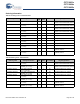
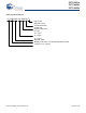
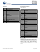
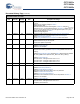
Document History Page
Document Title: CY7C6431x, CY7C6434x, CY7C6435x, enCoRe™ V Full Speed USB Controller
Document Number: 001-12394
Rev. ECN No.
Orig. of
Change
Submission
Date
Description of Change
** 626256 TYJ See ECN New data sheet.
*A 735718 TYJ / ARI See ECN Filled in TBDs, added new block diagram, and corrected some values. Part
numbers updated as per new specifications.
*B 1120404 ARI See ECN Corrected the block diagram and Figure 3, which is the 16-pin enCoRe V
device. Corrected the description to pin 29 on Table 2, the Typ/Max values for
I
SB0
on the DC chip-level specifications, the current value for the latch-up
current in the Electrical Characteristics section, and corrected the 16 QFN
package information in the Thermal Impedance table.
Corrected some of the bulleted items on the first page.
Added DC Characteristics–USB Interface table.
Added AC Characteristics–USB Data Timings table.
Added AC Characteristics–USB Driver table.
Corrected Flash Write Endurance minimum value in the DC Programming
Specifications table.
Corrected the Flash Erase Time max value and the Flash Block Write Time
max value in the AC Programming Specifications table.
Implemented new latest template.
Include parameters: Vcrs, Rpu (USB, active), Rpu (USB suspend), Tfdeop,
Tfeopr2, Tfeopt, Tfst.
Added register map tables.
Corrected a value in the DC Chip-Level Specifications table.
*C 1241024 TYJ / ARI See ECN Corrected Idd values in Table 6 - DC Chip-Level Specifications.
*D 1639963 AESA See ECN Post to www.cypress.com
*E 2138889 TYJ /
PYRS
See ECN Updated Ordering Code table:
- Ordering code changed for 32-QFN package: From -32LKXC to -32LTXC
- Added a new package type – “LTXC” for 48-QFN
- Included Tape and Reel ordering code for 32-QFN and 48-QFN packages
Changed active current values at 24, 12 and 6MHz in table “DC Chip-Level
Specifications”
- IDD24: 2.15 to 3.1mA
- IDD12: 1.45 to 2.0mA
- IDD6: 1.1 to 1.5mA
Added information on using P1[0] and P1[1] as the I2C interface during POR
or reset events