
Specifications
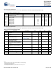
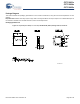

CY7C6431x
CY7C6434x
CY7C6435x
Document Number: 001-12394 Rev. *R Page 26 of 40
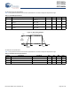
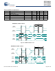
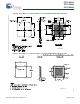
Figure 14. SPI Master Mode 0 and 2
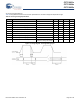
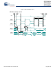
Figure 15. SPI Master Mode 1 and 3
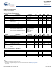
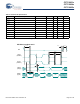
Table 22. SPI Master AC Specifications
Symbol Description Conditions Min Typ Max Units
F
SCLK
SCLK clock frequency – – 6 MHz
DC SCLK duty cycle – 50 – %
T
SETUP
MISO to SCLK setup time 60 – – ns
T
HOLD
SCLK to MISO hold time 40 – – ns
T
OUT_VAL
SCLK to MOSI valid time – – 40 ns
T
OUT_H
SCLK to MOSI hold time 40 – – ns
1/F
SCLK
T
LOW
T
HIGH
T
OUT_H
T
HOLD
T
SETUP
T
OUT_SU
MSb
LSb
SPI Master, modes 0 and 2
SCLK
(mode 0)
SCLK
(mode 2)
MISO
(input)
MOSI
(output)
1/F
SCLK
T
HIGH
T
LOW
T
OUT_H
T
HOLD
T
SETUP
SCLK
(mode 1)
SCLK
(mode 3)
MISO
(input)
MOSI
(output)
SPI Master, modes 1 and 3
T
OUT_SU
MSb
MSb
LSb
LSb