
User manual

CY8C27143, CY8C27243
CY8C27443, CY8C27543, CY8C27643
Document Number: 38-12012 Rev. *O Page 38 of 53
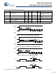
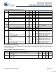
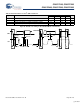
AC External Clock Specifications
The following tables list guaranteed maximum and minimum specifications for the voltage and temperature ranges: 4.75V to 5.25V
and -40°C ≤ T
A
≤ 85°C, or 3.0V to 3.6V and -40°C ≤ T
A
≤ 85°C, respectively. Typical parameters apply to 5V and 3.3V at 25°C and
are for design guidance only.
SR
ROB
Rising Slew Rate (20% to 80%), 1V Step, 100 pF Load
Power = Low
Power = High
0.65
0.65
–
–
–
–
V/μs
V/μs
SR
FOB
Falling Slew Rate (80% to 20%), 1V Step, 100 pF Load
Power = Low
Power = High
0.65
0.65
–
–
–
–
V/μs
V/μs
BW
OB
Small Signal Bandwidth, 20mV
pp
, 3dB BW, 100 pF Load
Power = Low
Power = High
0.8
0.8
–
–
–
–
MHz
MHz
BW
OB
Large Signal Bandwidth, 1V
pp
, 3dB BW, 100 pF Load
Power = Low
Power = High
300
300
–
–
–
–
kHz
kHz
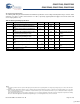
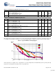
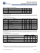
Table 37. 5V AC Analog Output Buffer Specifications (continued)
Symbol Description Min Typ Max Unit
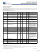
Table 38. 3.3V AC Analog Output Buffer Specifications
Symbol Description Min Typ Max Unit
T
ROB
Rising Settling Time to 0.1%, 1V Step, 100 pF Load
Power = Low
Power = High
–
–
–
–
3.8
3.8
μs
μs
T
SOB
Falling Settling Time to 0.1%, 1V Step, 100 pF Load
Power = Low
Power = High
–
–
–
–
2.6
2.6
μs
μs
SR
ROB
Rising Slew Rate (20% to 80%), 1V Step, 100 pF Load
Power = Low
Power = High
0.5
0.5
–
–
–
–
V/μs
V/μs
SR
FOB
Falling Slew Rate (80% to 20%), 1V Step, 100 pF Load
Power = Low
Power = High
0.5
0.5
–
–
–
–
V/μs
V/μs
BW
OB
Small Signal Bandwidth, 20mV
pp
, 3dB BW, 100 pF Load
Power = Low
Power = High
0.7
0.7
–
–
–
–
MHz
MHz
BW
OB
Large Signal Bandwidth, 1V
pp
, 3dB BW, 100 pF Load
Power = Low
Power = High
200
200
–
–
–
–
kHz
kHz
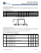
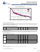
Table 39. 5V AC External Clock Specifications
Symbol Description Min Typ Max Unit
F
OSCEXT
Frequency 0.093 – 24.6 MHz
– High Period 20.6
– 5300 ns
– Low Period 20.6
– –ns
– Power Up IMO to Switch 150
– –
μ
s
Notes
19. Maximum CPU frequency is 12 MHz at 3.3V. With the CPU clock divider set to 1, the external clock must adhere to the maximum frequency and duty cycle
requirements.
20. If the frequency of the external clock is greater than 12 MHz, the CPU clock divider must be set to 2 or greater. In this case, the CPU clock divider ensures that the
fifty percent duty cycle requirement is met.
21. For the full industrial range, the user must employ a temperature sensor user module (FlashTemp) and feed the result to the temperature argument before writing.
Refer to the Flash APIs Application Note AN2015 at http://www.cypress.com under Application Notes for more information.
[+] Feedback