
Specifications


5. Demonstration Projects LIN Bus 2.0 Reference Design
54 Cypress Semiconductor – Rev. ** October 25, 2006
if(bResponseError) BufferFrame2[2] |= RESPONSE_ERROR_MASK;
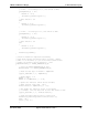
// Process Frame3. This frame is an Event triggered one. So look if there
// has been any change in value on the switches connected to Port2. Only if
// there is a change, update the Frame3 buffer with the new value and also
// set the bfDATA_READY flag in the first byte of the buffer, so that next
// time the Master sends this frame, the slave will respond with the updated
// switch value
if (PreviousValue != PRT2DR)
{
PreviousValue = PRT2DR;
TempBuffer[1] = PRT2DR;
TempBuffer[0] = bfDATA_READY;
l_bytes_wr(Frame3, 0, 2, TempBuffer);
}
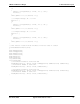
/* Uncomment this section if Goto Sleep function is desired
// Check if the Goto Sleep Flag has been set. If set, call the GoToSleep Function
if(TransferStatus & bfSTATUS_GOTO_SLEEP)
{
GoToSleep();
}
*/
}// End of While loop
}
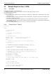
5.5 Example Project for Slave 2 (DIA)
5.5.1 Description
Following are the functions performed by slave 2:
1. Initialize the hardware resources for the indicator LEDs, DIP switches and the LIN core.
2. Clear the response error bit.
3. Inside an infinite Loop:
❐ Update Frame1 (VL1_DIA_Frm1) buffer with the status of SW1 and SW2.
❐ Check if Frame2 (VL1_CEM_Frm2) is complete. If yes, check the status of SW7 and SW8 of slave 1 sent in this frame
and control the blinking LEDs accordingly.
❐ Check if the GOTO_SLEEP flag has been set. If yes, enter the low-power mode.
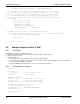
5.5.2 Example Slave 2 Program
void main()
{
// Initialize LIN
l_ifc_init(); // Init LIN Physical core
bLinNAD = 2; // Init the NAD
// Initialize Parameters
PRT0DR = 0x24; // Make Switch Inputs Pull Up
PRT1DR = 0x00; // Switch off LED1 and LED2
IndicatorFlag = 0; // Clear the Indicator flags
// Initialize Status bytes of all frames
// Clear the Response Error bit
BufferFrame1[0] = 0 | bfRESPONSE_ERROR_BYTE;
BufferFrame2[0] = 0;
Indicator_Start();