
Specifications


4. Slave Design IP LIN Bus 2.0 Reference Design
36 Cypress Semiconductor – Rev. ** October 25, 2006
regardless of which configuration is active, the GPIO state of
your main application is maintained. When you complete
this process, the TX and RX pins configuration looks like the
information in this table:
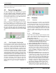
4.6.4 Routing the Signals
The next step is to route the signals to the digital blocks of
the LIN configurations.
1. Switch to Synchro Reception Configuration.
2. Route the RX Global_Input net to an appropriate
Row_1_Input_x line.
3. Select “Async” inside the Sync select square.
4. Select this Row_1_Input_x as the Capture input of the
Synchro_timer.
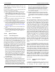
5. Switch to Data Reception Configuration.
6. Route the RX Global_Input net to the same
Row_1_Input_x net selected in the Synchro Reception
Configuration.
7. Select “Async” inside the Sync select square.
8. Select this Row_1_Input_x as the input to the RX8 User
Module.
9. Route the output of the TX8 User Module through an
appropriate Row_1_Output_x line to the TX
Global_Output net.
10. Switch to the base configuration
11. Make the connection between the Global_Input net and
the Row_1_Input_x net as done in the Data Reception
Configuration.
12. 12. Make the connection between the Row_1_Output_x
net and the Global_Output net in the Data Reception
Configuration.
With this routing of signals, the hardware configuration is
complete.
Note that in the LIN design for the CY8C21x34 family, the
same digital block used for RX8 is reconfigured into TX8 in
software during data transmission. So while using the
CY8C21x34 family, decide which Row Output net in which to
route the TX signal to a Global Out bus. Connect the output
of that Row Output net to the required Global Out bus in the
Data Reception Configuration and connect the Global Out
bus to the TX pin. Then, in the lin20slave.inc header file, set
the appropriate ROW_OUTPUT_x equate to 1. While the
Data Reception Configuration is loaded, the RX8 block is
configured into a TX8 block and the primary output is con-
nected to the specified Row Output net.
4.6.5 Configuring the Signal Table
You must configure the frames that belong to the slave. This
is done in the signaltable.asm file using the node capability
file or the LDF in which this node is described. For this
example, refer to the LDF provided in section 5, LIN
Description File (LDF) on page 43.
This example configures the slave CPM. As described in the
LDF file, this slave has three frames.
■ VL1_CEM_Frm1: This frame is published by the master
and is subscribed to by this slave. The message ID of
this frame is 0x1001. The length of this frame is eights
bytes.
■ VL1_CPM_Frm1: This frame is published by this slave
and is subscribed to by the master. The message ID of
this frame is 0x1002. The length of this frame is two
bytes.
■ VL1_CPM_Frm2: This frame is published by this slave
and is subscribed to by the master. The message ID of
this frame is 0x1003. The length of this frame is one
byte.
4.6.5.1 RAM Allocation
First, the buffers for these frames are allocated in RAM. A
name is given to each frame and the buffer is named as
Buffer<FrameName>. In our example, name the frames as
Frame1, Frame2 and Frame3. The buffers for these frames
are BufferFrame1, BufferFrame2, BufferFrame3. When allo-
cating RAM, one extra byte is allocated for each frame. This
byte is used as the status byte of that particular frame. The
LIN firmware updates the transaction status of each frame in
this byte. This byte also has the flag that indicates if a partic-
ular frame carries the Response_Error bit. This byte is the
first byte of the array. Apart from these buffers, there is
another buffer used by the LIN firmware for diagnostic
frames. This buffer is named as “abDiagBuffer.” Because
this buffer is only used during node configuration, it reuses
the same RAM location used by other frames. In the exam-
ple below, the abDiagBuffer reuses the RAM of
BufferFrame1. If the application requires the frame signals
preserved during node configuration, then allocate nine
bytes for this buffer. If the total RAM for all the signals is less
than nine bytes, then also allocate nine bytes for the abDi-
agBuffer.
_abDiagBuffer:
abDiagBuffer:
_BufferFrame1:
BufferFrame1: blk 9
_BufferFrame2:
BufferFrame2: blk 3
_BufferFrame2:
BufferFrame2: blk 2
Table 4-1. TX Pin
Configuration Name Port Select Drive Interrupt
Base TX As selected GlobalOut Strong DisableInt
Synchro Reception TX As selected StdCPU High Z DisableInt
Data Reception TX As selected GlobalOut Strong DisableInt
Table 4-2. RX Pin
Configuration Name Port Select Drive Interrupt
Base RX As selected GlobalIn High Z DisableInt
Synchro Reception RX As selected GlobalIn High Z Change-
FromRead
Data Reception RX As selected GlobalIn High Z DisableInt