
Specifications


3. Master Design IP LIN Bus 2.0 Reference Design
22 Cypress Semiconductor – Rev. ** October 25, 2006
Once the frame definition and the buffer allocations are
complete, export these names as Global so they are used in
the main application and the LIN API. All the frame names
and buffer names must be declared with and without an
underscore. The name with the underscore is to enable the
name to be used in C functions. For the above example, the
following names are exported.
export _MasterRequest
export MasterRequest
export _SlaveResponse
export SlaveResponse
export _Frame1
export Frame1
export _Frame2
export Frame2
export _Frame3
export Frame3
export _Frame4
export Frame4
export _abDiagBuffer
export abDiagBuffer
export _BufferFrame1
export BufferFrame1
export _BufferFrame2
export BufferFrame2
export _BufferFrame3
export BufferFrame3
export _BufferFrame4
export BufferFrame4
Once these names are exported, they are available to any
assembly function. To use these names in C, they must be
declared in a C header file. This is done in the SignalTable.h
file. All frame names are defined as “const char” as they are
in the Flash and the buffer names are defined as “BYTE” as
they are in the RAM. The following are the entries in the
SignalTable.h file.
// Definition of Frame Buffers to be used by
the main program
extern BYTE BufferFrame1[];
extern BYTE BufferFrame2[];
extern BYTE BufferFrame3[];
extern BYTE BufferFrame4[];
extern BYTE abDiagBuffer[];
// Definition of Frame names to be used by
the main program
extern const char Frame1[];
extern const char Frame2[];
extern const char Frame3[];
extern const char Frame4[];
3.6.11 Schedule Table
3.6.11.1 Structure of Schedule Table
Once the frames used in the cluster are defined, you need
to create Schedule tables. The Schedule tables are found in
the “ScheduleTable.asm” file. To create a Schedule table,
you first select a name. For the example, create a Schedule
table called Schedule1. The table entries are entered in this
order.
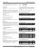
A. Frame Name: The name of the frame to be transmitted.
B. Frame Time Constant: The number of schedule timer
interrupts before the next frame is transmitted. This
value is derived from the “Node Capability File” of the
nodes. The node capability file has frames defined with
minimum and maximum frame times. If these values are
not given in the node capability file, then use the formula
given in “Section 2.2 Frame Slots” in the LIN 2.0 protocol
specification. The equations are:
T
Header Nominal
= 34 * T
Bit
Equation 1
T
Respone Nominal
= 10 * (N
Data
+1) * T
Bit
Equation 2
T
Frame Nominal
= T
Header Nominal
+ T
Respone
Nominal
Equation 3
This calculation does not consider the response space, byte
space or inter-frame space. The actual time used is accord-
ing to the LIN 2.0 protocol specification.
T
Frame Maximum
= 1.4 * T
Frame Nominal
Equation 4
From this time, calculate the number of schedule timer over-
flows based upon the schedule timer time base.
Frame Time Constant = Frame Time / Timebase
For example, if the frame time is calculated as 20 ms and
the time base is 1 ms, then the frame time constant is 20 ms
/ 1mS = 20.
_MasterRequest:
MasterRequest:
db CSUM_CLASSIC ; Checksum Type
db 8 ; Data count
db abDiagBuffer ; Buffer address
db MASTER_TO_SLAVE ; Direction
db 0x3C ; ID
_SlaveResponse:
SlaveResponse:
db CSUM_CLASSIC ; Checksum Type
db 8 ; Data count
db abDiagBuffer ; Buffer address
db SLAVE_TO_MASTER ; Direction
db 0x7D ; ID