
Specifications


3. Master Design IP LIN Bus 2.0 Reference Design
20 Cypress Semiconductor – Rev. ** October 25, 2006
8. Select Row_1_Input_x (step 7) as the input to the RX8
User Module.
9. Switch to the base configuration.
10. Make the connection from Row_1_Output_x net to the
Global bus as used by the Data Transmission and Syn-
chro Break configurations in the base configuration.
11. Make the connection from Global_In bus to the
Row_1_Input_x net as used by the Data Reception Con-
figuration.
With this routing of signals, the hardware configuration is
complete.
3.6.5 Setting the Baud Rate
In the Lin20Master.inc file, there are four constants:
BR2400, BR4800, BR9600, and BR19200. These corre-
spond to 2.4K, 4.8K, 9.6K, and 19.2K baud rates, respec-
tively. Set the value of one of these constants to 1 to
correspond to the baud rate. This constant is used to select
the period and compare values of the baud rate generator.
Make only one of these constants 1.
3.6.6 Adding the Schedule Timer
An important module necessary for the proper functioning of
the master is the schedule timer. This timer is used to gener-
ate the frame slot timings for the LIN bus. This is placed by
the user in the base configuration. Follow these steps.
1. Go to the base configuration.
2. Select a Counter8 User Module and add it to the project.
3. Rename it “ScheduleTimer.”
4. Place it in any of the available digital blocks. Avoid plac-
ing it in a digital block used by the LIN design in any of
the other configurations.
5. Configure the parameters for the counter as:
❐ Clock: according to the time base
❐ Enable: High
❐ CompareOut: None
❐ TerminalCountOut: None
❐ Period: As per time base
❐ CompareValue: ½ (Period + 1)
❐ CompareType: Less Than or Equal To
❐ InterruptType: Terminal Count
❐ ClockSync: As per the Clock source
❐ InvertEnable: Normal
3.6.7 Setting the Source Clock and
Period
Set the source clock and period according to the time base
specified in the LDF. In the example, the time base is 1 ms.
Make the counter output frequency 1 kHz. Since the config-
uration of the clock resources is very flexible, there are dif-
ferent combinations of clock source and period that
arepossible. For example:
■ Clock: VC2.
■ VC2 Divider = 10. As VC1’s divider is already set to 12
by the LIN firmware, the output frequency of VC2 is 200
kHz.
■ Period = 199. VC2 is divided by (Period + 1), i.e., 200 to
give an output frequency of 1 kHz.
3.6.8 Configuring the Signal Table
You now need to configure the frames used in the system in
the SignalTable.asm file. This configuration is done accord-
ing to the LDF. For this example, refer to the LDF provided in
section 5, LIN Description File (LDF) on page 43. According
to the LDF file, a total of four frames are used.
■ VL1_CEM_Frm1: This frame is published by the master
and is subscribed to by the slaves CPM and DIA. The
protected ID for this frame is 0xF0. The length of this
frame is eight bytes.
■ VL1_CPM_Frm1: This frame is published by slave CPM
and is subscribed to by the master. The protected ID of
this frame is 0x9C. The length of this frame is two bytes.
■ VL1_CPM_Frm2: This frame is published by slave CPM
and is subscribed to by the master. The protected ID of
this frame is 0x32. The length of this frame is one byte.
■ VL1_DIA_Frm1: This frame is published by slave DIA
and is subscribed to by the master. The protected ID of
this frame is 0x80. The length of this frame is two bytes.
3.6.9 RAM Allocation
First the buffers for these frames are allocated in RAM. A
name is given to each frame and the buffer is named as
Buffer<FrameName>. The frames are named Frame1,
Frame2, Frame3, and Frame4. The buffers for these frames
are BufferFrame1, BufferFrame2, BufferFrame3, and
BufferFrame4. When assigning RAM, one extra byte is allo-
cated for each frame. This byte is used as the status byte of
that particular frame. The LIN firmware updates the status of
transaction of each frame in this byte. The status byte is the
first byte of the array. Another buffer is used by the LIN firm-
ware for diagnostic frames. This buffer is named “abDiag-
Buffer.” The diagnostic frames always carry eight bytes. This
makes the total length of this buffer nine bytes.
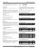
Here is an example of RAM allocation.
area bss(ram)
_abDiagBuffer:
abDiagBuffer: BLK 9; Buffer for Diagnostic
frames
_BufferFrame1:
BufferFrame1: BLK 9; Buffer for Frame1
_BufferFrame2:
BufferFrame2: BLK 3; Buffer for Frame2
_BufferFrame3:
BufferFrame3: BLK 2; Buffer for Frame3
_BufferFrame4:
BufferFrame4: BLK 2; Buffer for Frame4
3.6.10 Frame Definition
Now the frames are defined in the Signal table. Each frame
has the following parameters entered in this order: