
User's Manual
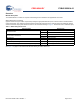
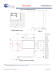
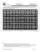
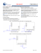
Table Of Contents
- EZ-BLE™ PRoC™ Bluetooth 4.2 Module
- General Description
- Benefits
- More Information
- Contents
- Overview
- Pad Connection Interface
- Recommended Host PCB Layout
- Power Supply Connections and Recommended External Components
- Electrical Specification
- Environmental Specifications
- Regulatory Information
- Packaging
- Ordering Information
- Acronyms
- Document Conventions
- Document History Page
- Sales, Solutions, and Legal Information

PRELIMINARY
CYBLE-222014-01
Document Number: 002-11186 Rev. ** Page 8 of 37
Table 3 provides the center location for each solder pad on the CYBLE-222014-01. All dimensions reference the to the center of the
solder pad. Refer to Figure 6 for the location of each module solder pad.
Table 3. Module Solder Pad Location Figure 6. Solder Pad Reference Location
Solder Pad
(Center of Pad)
Location (X,Y) from
Orign (mm)
Dimension from
Orign (mils)
1 (0.26, 1.64) (10.24, 64.57)
2 (0.26, 2.41) (10.24, 94.88)
3 (0.26, 3.17) (10.24, 124.80)
4 (0.26, 3.93) (10.24, 154.72)
5 (0.26, 4.69) (10.24, 184.65)
6 (0.81, 9.74) (31.89, 383.46)
7 (1.57, 9.74) (61.81, 383.46)
8 (2.34, 9.74) (92.13, 383.46)
9 (3.10, 9.74) (122.05, 383.46)
10 (3.86, 9.74) (151.97, 383.46)
11 (4.62, 9.74) (181.89, 383.46)
12 (5.38, 9.74) (211.81, 383.46)
13 (6.15, 9.74) (242.13, 383.46)
14 (6.91, 9.74) (272.05, 383.46)
15 (7.67, 9.74) (301.97, 383.46)
16 (8.43, 9.74) (331.89, 383.46)
17 (9.19, 9.74) (361.81, 383.46)
18 (9.75, 8.50) (383.86, 334.65)
19 (9.75, 7.74) (383.86, 304.72)
20 (9.75, 6.98) (383.86, 274.80)
21 (9.75, 6.22) (383.86, 244.88)