
User Manual
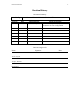
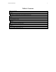
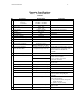
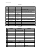
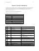
Table Of Contents

Instruction Manual 9
Receiver
No. Parameter Requirement Comments
1 Passband Ripple 1dB Measured at baseband, 400Hz to 9.2kHz
2 Total Group Delay
75µsec (max)
Measured at baseband, 400Hz to 9.2kHz
3 Differential Group Delay TBD Measured at baseband between the I and Q
channels, 400Hz to 9.2kHz
4 I Q Gain Imbalance 0.5dB Measured at baseband, 400Hz to 9.2kHz
5 I Q Phase Imbalance
≤ 2°
Measured at baseband, 400Hz to 9.2kHz
6 DC Offset
≤ 10% minimum
signal level
≅ 216µVrms at 14dB S/N
7 Output Noise 3 bits @
53.95µV/bit
≅ 432µVrms, Measured at the ADC input
8 Noise Figure 5dB min
9 Sensitivity -119dBm
≅ 0.25µVrms, Measured at the receiver input
Power of 1 sub-channel.
10 Adjacent Channel
Rejection Ratio
80dB min
11 3
rd
order Intermodulation
Distortion
5dBm min
Interferer tones at F
0
± 50kHz and ± 100kHz
12 Image Rejection 100dB min
13 ½ IF Rejection 100dB min
14 Spurious Rejection 100dB min
15 Gain Variation 15dB Adjustable for site noise variations
16 ADC 16 bit Serial output, single ended, 52kHz sample rate
17 Dynamic Range 65dB 16bits – 3.5 noise bits → 12 bits, with a 14dB S/N
Transmitter
No. Parameter Requirement Comments
1 Emission Designator 18K4D7W
2 Emission Mask §90.691 for 851-866 MHz
§90.210B for 866-869 MHz
3 Modulation
DC/MA
16QAM (2 level 8 phase) Digital
Channel/Multicarrier Architecture
4 Output Power 90 Watts Continuous Average DC/MA has a 10dB Peak to Average
Ratio
5 Output Impedance
50 Ω
6 Image Suppression -55dBc Image measured at the output of the
transmitter.
7 Amplitude Response
<1.0dB
Measured across the 18MHz Tx band
8 Intermodulation Products -60dBc DC/MA intermodulation performance
measured at the output of the
transmitter
9 Tuning Spacing 12.5kHz
10 Channel Frequency spread 18MHz
11 Occupied Bandwidth 20kHz
12 LO Phase Noise -85dbc/Hz @ 400Hz
–126dBc/Hz @ 10kHz
–134dBc/Hz @ 25kHz
Single sideband phase noise
13 LO Reference Spur
< -98dBc @ 12.5kHz
Maximum level for the 12.5kHz
reference spur