
User Manual
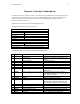
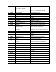
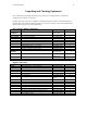
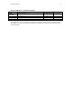
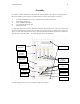

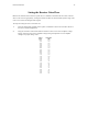
Table Of Contents
Instruction Manual 16
The assembly steps are as follows:
1) The two AC Power Distribution units (Tripp-Lite, IBAR 12/20 Ultra) should be mounted first. In a
rack-based system, they will be mounted in the rear of the rack and in relay rack-based system, they
will be mounted at the top of the front of the rack. In either case, they must be mounted in close
proximity to the Power Supply Subsystem as the interconnect cabling between the units is on the order
of one foot.
2) The Power Supply Subsystem (075-00028-0001) should be mounted in the rack next. Space should be
left for later installation of a 1U blank panel (300-00056-0001) which is installed above the Power
Supply Subsystem. As previously noted, the Power Supply Subsystem must be in close proximity to
the AC Power Distribution units.
3) The interconnecting cables (060-00053-0001) between the AC Power Distribution and the Power
Supply Subsystem enclosure should be installed next.
4) The Power Amplifier Subsystem enclosure (MR860-41S) should be mounted in the rack next.
5) With the Power Amplifier Subsystem enclosure in place, the four RF power amplifiers (MAF860-25S)
should be inserted in the enclosure and retained in place with the captive hardware.
6) The Low-Level RF enclosure (075-00027-0001) should be installed next.
7) The Digital Enclosure with backplane (075-00026-0001) should be installed next.
8) The Fan Tray (Comair Rotron 31038) should be installed next.
9) The two 1U blank panels (300-00056-0001) should be installed at the top and bottom of the installed
units.
10) With the subsystem enclosures in place, install the following cables:
a) PA Power Cable (060-00016-0001)
b) LLRF Power Cable - +/- 15 VDC(060-00025-0001)
c) Digital Power Cable (060-00024-0001)
d) Digital Power Cable - +/- 12 VDC (060-00026-0001)
e) Digital Power Sense Cable (060-00023-0001)
f) Trunking Controller Power Cable (060-00032-0001)
11) With the Digital Enclosure installed, the digital cards must be inserted in the following order:
Note: Proper grounding practice should be followed while inserting all of the digital cards.
a) The Repeater Controller (050-00003-0200) must be inserted into slot one.
b) The Tx master (050-00004-0203) must be inserted into slot two.
c) The Rx master (050-00004-0201) must be inserted into slot three.
d) The two Rx Slaves (050-00004-0202) must be inserted into slots four and five.
e) The four Channel Cards (050-00023-0200) must be inserted into slots eight through eleven.
12) Install the following interconnect cables:
a) Exciter Signal Cable (060-00040-0001)
b) RF/Digital DB-25 Communications Cable (060-00051-0001)
c) RF/Digital DB-9 Communications Cable – to PA (060-00055-0001)
d) RF/Digital DB-9 Communications Cable – to LLRF (060-00042-0001)
e) RF/Digital Coaxial 13MHz Reference Cable (060-00034-0001)
f) Two Trunking Controller DB-15 cables (short length) (060-00049-0001)
g) Three Trunking Controller DB-15 cables (medium length) (060-00049-0002)
h) Three Trunking Controller DB-15 cables (long length) (060-00049-0003)