
User Manual
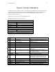
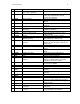
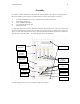
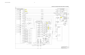

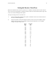
Table Of Contents

Instruction Manual 14
Assembly
The repeater should be assembled as indicated in the following diagram. The repeater, excluding elements
like trunk controllers, LAN interface, and modem that are not shown in the diagram, consists of:
1) AC Power Distribution (not shown – mounted in rear of rack-based system),
2) Power Supply Subsystem,
3) Power Amplifier Subsystem,
4) Low-Level RF Subsystem, and
5) Digital Subsystem.
In a rack-based system, the AC Power Distribution should be mounted in the rear of the rack enclosure with
the other four subsystems mounted in the front of the rack enclosure from top-to-bottom in the order listed
above. In a relay rack-based system, all five components/subsystems should be mounted top-to-bottom in a
relay rack in the order listed above. The following figure shows the rack layout.
The following figure shows the interconnection wiring for the repeater.
Power Supply
Subsystem
Power
Amplifier
Subsystem
Low-Level RF
Subsystem
Digital
Subsystem
Power
Am
p
lifiers
Blank Panels
Channel
Cards
RX Slaves
RX Master
TX Master
Repeater
Cont
r
olle
r
Fan Tray