
User Manual

Instruction Manual 12
Assembly
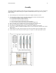
The repeater should be assembled as indicated in the following diagram. The RF power unit, containing the
power supplies, low level RF and RF power amplifiers should be mounted in a relay rack on top of the
digital card cage.
1) After the RF power unit is mounted, the four RF power amplifiers should be inserted
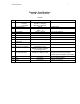
2) After mounting the digital card cage, the digital cards must be inserted in the following order.
a) The Repeater Controller must be inserted into slot one.
b) The Tx master must be inserted into slot two.
c) The Rx master must be inserted into slot three.
d) The two Rx Slaves must be inserted into slots four and five.
e) The four Channel Cards must be inserted into slots eight through eleven.
3) Proper grounding practice should be followed while inserting all of the digital cards.
4) The relay rack should be grounded to a properly installed building ground.
5) Two AC lines of a minimum 20Amp service at 115V must be available for the repeater.
6) Connect the two DB-25, the DB-9 and 13MHz-reference coaxial cable between the RF chassis and the
digital chassis.
7) Connect the power supply cable and voltage sense cable from the RF chassis to the digital chassis.
8) Connect the Rx and Tx connection from the repeater to a duplexer or multicoupler/splitter system.