
User manual


CyBro-2 and all its expansions except OP-2, should be mounted vertically onto the standard DIN rail
(DIN EN 50022), on a metal plate, within a suitable enclosure, like a cabinet (key or tool entry).
Total power dissipation of CyBro-2 and other devices inside enclosure (cabinet) must not exceed
permissible power dissipation of enclosure.
CyBro-2 is designed for natural convection cooling. You must provide a clearance of at least 30 mm,
both above and below the units, for proper cooling.
Open the DIN clip to allow mounting, and snap
close to secure the unit on the rail.
When connecting the units by using the shortest
IEX-2 connection cables, snap the cable to the left
unit first, and then snap the right unit onto the
cable.
When the units are connected together, the distance
between them is very small.
Use the small screwdriver to press cable connector
clip and pull the unit away to disconnect.
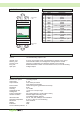
For mounting OP-2 at the control panel, use special
self-tapping screws for plastic 3xL.
L=(control panel thickness+9mm)±4mm
Drilling template is given on the last page of this
manual.
rubber seal
(optional)
L
control panel
view
direction
2. pull
1. push
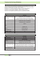
Use this product in an environment as described in this document.
If this product is subject to high temperature, high humidity, excessive dust, corrosive gases, vibration
or shock, it may result in an electric shock, fire or malfunction.
Install this product according to instructions in this manual.
If installation is not performed correctly, it may result in unit failing or malfunction.
Do not allow foreign objects as wire chips to enter the unit.
This may cause fire, unit failure or malfunction.
Caution
25
Mounting