
User guide


9
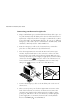
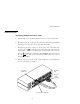
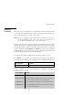
Attaching Multiple AutoView Units
1. Follow steps 1-9 of the Basic Install section for each cascaded unit.
2. Plug the 25-pin “D” connector of your input cable into any available
channel port on the rear of your base AutoView unit.
3. Plug the 15-pin video connector on the other end of the cable into
the port labeled
on your first cascading AutoView unit. Plug the
PS/2 mouse connector, designated by a yellow band or mouse icon,
into the
port. Plug the remaining 6-pin miniDIN keyboard connector
into the
port. The 9-pin serial and 5-pin DIN connectors are not
used for cascading.
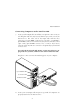
4. Repeat steps 9-12 in the ‘Connecting Computers to the AutoView
200’for each attached compter.
Advanced Install
Basic Installation
H
POWER
100-240V~, .1a, 50/60Hz
FDB
H
POWER
100-240V~, .1a, 50/60Hz
FDB
CASCADING
UNIT
PS/2 KEYBOARD CONNECTOR
PS/2 MOUSE
CONNECTOR
BASE UNIT
VIDEO
CONNECTOR