AutoView® 200/400 Installer/User Guide
INSTRUCTIONS This symbol is intended to alert the user to the presence of important operating and maintenance (servicing) instructions in the literature accompanying the appliance. DANGEROUS VOLTAGE This symbol is intended to alert the user to the presence of uninsulated dangerous voltage within the product’s enclosure that may be of sufficient magnitude to constitute a risk of electric shock to persons. POWER ON This symbol indicates the principal on/off switch is in the on position.
AutoView® 200/400 Installer/User Guide Avocent, the Avocent logo and The Power of Being There are trademarks of Avocent Corporation. AutoView and LongView are registered trademarks of Cybex Computer Products Corporation. All other marks are the property of their respective owners. © 2002 Avocent Corporation. All rights reserved.
USA Notification Warning: Changes or modifications to this unit not expressly approved by the party responsible for compliance could void the user's authority to operate the equipment. Note: This equipment has been tested and found to comply with the limits for a Class A digital device, pursuant to Part 15 of the FCC Rules. These limits are designed to provide reasonable protection against harmful interference when the equipment is operated in a commercial environment.
Table of Contents Chapter 1: Product Overview Features and Benefits . . . . . . . . . . . . . . . . . . . . . . . . . 3 Compatibility . . . . . . . . . . . . . . . . . . . . . . . . . . . . . . . 6 Safety Precautions . . . . . . . . . . . . . . . . . . . . . . . . . . . 6 Chapter 2: Installation Getting Started . . . . . . . . . . . . . . . . . . . . . . . . . . . . . . 9 Rack Mounting your AutoView Unit . . . . . . . . . . . . 9 Installing an AutoView Switch . . . . . . . . . . . . . . . .
1 Product Overview Contents Features and Benefits . . . . . . . . . . . . . . . . . . . . . . . . . 3 Compatibility . . . . . . . . . . . . . . . . . . . . . . . . . . . . . . . 6 Safety Precautions . . . . . . . . . . . . . . . . . . . . . . . . . . .
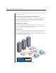
Chapter 1: Product Overview 3 Chapter 1: Product Overview Features and Benefits The AutoView 200 and 400 series KVM switches allow you to control multiple computers from one keyboard, monitor and mouse. The AutoView 200 allows you to control up to 64 PCs, while the AutoView 400 enables control of up to 64 PC, Sun or USB computers. Both models work with IBM PC/AT, PS/2 systems and 100% compatible machines with support for VGA, SVGA, XGA and XGA-II video.
4 AutoView 200/400 Installer/User Guide With the AutoView 400 switch, your PS/2 mouse will also control Sun and USB computers seamlessly. Advanced security for total control over system access Use the advanced multilevel security feature to configure and control server access for every type of user in the system. The administrator has full access privileges, while individual users can have viewing or viewing/editing capability for each attached server.
Chapter 1: Product Overview 5 OSD Configuration Utility The OSD Configuration Utility allows the administrator to easily configure and download a channel list with defined users and access privileges to the entire system. This utility will also read and save your current configuration for extra security. Expansion for up to 64 computers Your AutoView unit will support from one to eight attached computers, or channels.
6 AutoView 200/400 Installer/User Guide Compatibility XGA/XGA-II support If you wish to use XGA or XGA-II video, you will need to purchase an adaptor available through Avocent. Safety Precautions To avoid potential video and/or keyboard problems when using Avocent products: • If the building has 3-phase AC power, ensure that the computer and monitor are on the same phase. For best results, they should be on the same circuit. • Use only Avocent-supplied cable to connect computers and KVM switches.
2 Installation Contents Getting Started . . . . . . . . . . . . . . . . . . . . . . . . . . . . . . 9 Rack Mounting your AutoView Unit . . . . . . . . . . . . 9 Installing an AutoView Switch . . . . . . . . . . . . . . . . 11 Installing a Multiple Switch System . . . . . . . . . . . . 16 Powering Up the AutoView Switch System . . . . . .
Chapter 2: Installation 9 Chapter 2: Installation Getting Started Before installing your AutoView system, refer to the lists below to ensure that you have all the items that shipped with the AutoView as well as all other items necessary for proper installation.
10 AutoView 200/400 Installer/User Guide To install the rack mounting bracket: 1. Remove the side screws that secure the cover on your AutoView unit. 2. Line up the holes in the side brackets with the screw holes in the sides of the AutoView unit. 3. Using the previously removed screws, thread one through each of the holes in the sides of the rack mount brackets and into the AutoView cover. Tighten them securely. 4. Install a snap on nut (provided) onto one end of the cable support rod.
11 Chapter 2: Installation Installing an AutoView Switch Installing your AutoView 200 The diagram below illustrates one possible configuration for your AutoView 200 switch. Follow the step-by-step procedure To install an AutoView 200/400 switch to properly install your new switch. Extended Access User (via LongView) Local User For Sun Only –––+ 24VDC .5A RECEIVER For PS/2 Only REMOTE I/O AutoView 400 REMOTE USER LOCAL USER A C E G B D F H I/O SETUP 100-240V SUN , .
12 AutoView 200/400 Installer/User Guide Installing your AutoView 400 The diagram below illustrates one possible configuration for your AutoView 400 switch. Follow the step-by-step procedure To install an AutoView 200/400 switch to properly install your new switch. Extended Access User (via LongView) Local User For Sun Only –––+ 24VDC .5A RECEIVER For PS/2 Only REMOTE I/O AutoView 400 REMOTE USER LOCAL USER A C E G B D F H I/O SETUP 100-240V SUN , .
Chapter 2: Installation 13 To install an AutoView 200/400 switch: 1. Power down all computers that will be part of your AutoView system. 2. Plug your VGA monitor cable into the port labeled on the back of your AutoView. For Sun support, plug your Sun connector into the port labeled SUN and for PS/2 peripherals, plug your PS/2 keyboard cable and your PS/2 mouse cable into the ports labeled and respectively. 3.
14 AutoView 200/400 Installer/User Guide To connect an extended access Sun user station (AutoView 400 only): NOTE: This requires a VAK-1 adaptor kit available from Avocent. LongView –––+ 24VDC .5A RECEIVER REMOTE I/O VAK-1 Video Adaptor VAK-1 Keyboard/ Mouse Adaptor 13W3 Video Connector Keyboard/Mouse Connector Sun User Station Figure 2.4: Extended Access Sun User Station Installation 1. Plug a standard CAT 5 cable (up to 500 feet) into the RJ-45 modular jack on the rear of the AutoView.
Chapter 2: Installation 5. 15 If your extended access location utilizes Sun peripherals, you will need to set the AutoView 400 to recognize them before they can be used. To do this: a. b. c. d. Activate the OSD by pressing Control twice within one second. Press Control twice more to access Administrator Commands. Use your Arrow keys to highlight Administrator Functions and press Enter. Highlight Remote User.
16 AutoView 200/400 Installer/User Guide Installing a Multiple Switch System The following diagram illustrates one possible cascading configuration using your AutoView switch. Perform this installation if you want to add another switch to your existing system. Follow the step-by-step instructions to properly cascade your new AutoView switch. Local User AutoView 400 Primary Switch REMOTE USER LOCAL USER A C E G B D F H I/O SETUP 100-240V SUN , .
Chapter 2: Installation 17 To add a secondary switch to an AutoView switch system: NOTE: Cascading can only be done with CUFC, CIFC or CIFCA cables. 1. Follow the steps in the procedure To install an AutoView 200/400 switch for each cascaded unit. 2. Plug the 25-pin D connector of your CIFCM input cable into any available channel port on the rear of your primary AutoView unit. 3.
18 AutoView 200/400 Installer/User Guide
3 Basic Operations Contents Viewing and Selecting Channels and Servers . . . . 21 Setting up the On-Screen Display . . . . . . . . . . . . . . 23 Setting User Station Security . . . . . . . . . . . . . . . . . 28 Scanning your AutoView System . . . . . . . . . . . . . . 30 Resetting your Mouse . . . . . . . . . . . . . . . . . . . . . . . 33 Displaying Version Information . . . . . . . . . . . . . . . 33 Keyboard Switching . . . . . . . . . . . . . . . . . . . . . . . .
Chapter 3: Basic Operations 21 Chapter 3: Basic Operations Viewing and Selecting Channels and Servers Your AutoView may be operated in either a non-secure (no password required) or secure (password required) mode. All units ship defaulted to the non-secure mode. For more information on security, see Setting User Station Security in this chapter.
22 AutoView 200/400 Installer/User Guide and press Enter. The Administrator Channel List appears. -orIn secure mode, if you are the system administrator, log in as Admin, Root or Administrator. Type your password and press Enter. The Administrator Channel List appears. Avocent Control Panel Administrator Channel List Name Address Access Pam 1 VK John 2 V Elisabeth 3 VK Charlene 4 VK Sunshine 5 V Ann 6 VK ENTER = next ESC = exit Figure 3.2: The Administrator Channel List 3.
Chapter 3: Basic Operations 23 To select a channel in the OSD: 1. Use the Up or Down Arrow keys or the mouse to select a channel. -orPress the Home or End key to move directly to the top or bottom of the list. -orType a letter to move the highlight bar to the first channel name beginning with that letter. Press the letter repeatedly to scroll through all channels that begin with that letter from top to bottom. 2. Press Enter. To select servers without displaying the OSD: 1.
24 AutoView 200/400 Installer/User Guide Administrator Commands Features List Command Description Add Channel Set up the channel name, address, ID and scan dwell times. Edit Channel Edit the channel name, address, ID and scan dwell times. Delete Channel Delete a channel from the Administrator Channel List. Administrator Functions Set up administrator, users, channel switching, port setup and FLASH upgrade. Scanning Initiate the mode where the switch scans from port to port.
Chapter 3: Basic Operations 25 2. Press the keyboard Control key twice within one second again. The Administrator Commands menu appears. 3. Highlight Add Channel and press Enter. The Add Channel menu appears. Avocent Control Panel Add Channel Name Marketing Address C ID Dwell Time 5 Scan Dwell Time 5 ID Setup Save Changes ENTER = next ESC = exit Figure 3.4: Add Channel Menu 4. Type in a new channel name, up to 14 characters long, and press Enter. 5.
26 AutoView 200/400 Installer/User Guide Avocent Control Panel Edit Channel Name Marketing Address C ID Dwell Time 5 Scan Dwell Time 5 ID Setup Save Changes ENTER = next ESC = exit Figure 3.5: Edit Channel Menu 4. Type the new channel name, address, ID and scan dwell times. 5. Highlight ID Setup and press Enter. Use the Arrow keys to position the ID window where you would like it to appear when this channel is selected. Press Enter.
Chapter 3: Basic Operations 27 3. Highlight Edit Channel and press Enter. 4. Highlight ID Setup and press Enter. The ID window will appear. Follow the procedures outlined in the table below to configure your ID window. ID Window Settings To … Procedure Move the ID window Use the Arrow keys or mouse to move the ID window's position on the monitor. (Hold down the Shift key to move faster.) If the window flickers but does not move, continue pressing the Arrow keys until it moves back into range.
28 AutoView 200/400 Installer/User Guide Setting User Station Security The Administrator Functions menu allows you to set up the administrator and user accounts, enable and disable the setup port and utilize the AutoView FLASH upgrade feature. The following table discusses the security features. Security Operating Modes Feature Description Administrator Setting up an administrator account with a password places your system in secure mode.
Chapter 3: Basic Operations 29 To access the Administrator Functions menu: 1. Press the Control key twice to access the Administrator Channel List. 2. Press Control twice more to access the Administrator Commands menu. 3. Highlight Administrator Functions and press Enter. The Administrator Functions menu appears. To create the administrator account: 1. Press the Control key twice to access the Administrator Channel List. 2. Press Control twice more to access the Administrator Commands menu. 3.
30 AutoView 200/400 Installer/User Guide 8. Highlight one of the first three options and then press Enter to save your selections. 9. Repeat steps 3-7 for each remaining user. To assign the extended access user peripheral type (AutoView 400 only): 1. Press the Control key twice to access the Administrator Channel List. 2. Press Control twice more to access the Administrator Commands menu. 3. Highlight Administrator Functions - Remote User. 4.
Chapter 3: Basic Operations 31 scanning is suspended until all keyboard activity stops. Scanning then resumes with the next channel in sequence. The length of time each channel remains on the screen, or dwell time, is configurable and can be changed at any time. Scanning options You can scan through the channels in your AutoView system either by name, address or, on the AutoView 400, by list. NOTE: The AutoView only scans the computers that are in your OSD list.
32 AutoView 200/400 Installer/User Guide To scan using a keyboard hotkey sequence: See Keyboard Switching later in this chapter. To scan using the OSD menu: 1. Press the Control key twice to access the Administrator Channel List. 2. Press Control twice more to access the Administrator Commands menu. 3. Highlight Scanning. Use the Spacebar to toggle through the list of options: is Off, by Name, by Address or, on the AutoView 400, by List. 4. Press Enter to activate your selection.
Chapter 3: Basic Operations 33 configuration screen. 3. Press Enter to save the new entry. To remove a channel from the Scan List: 1. Use the Arrow keys to highlight the channel you wish to delete. 2. Press the F3 key. 3. Press Enter to confirm the deletion. Resetting your Mouse If your mouse locks up during normal use with the AutoView, you may be able to re-establish operation by issuing a reset command. The reset command sends a hot-plug sequence to the server.
34 AutoView 200/400 Installer/User Guide commands that can be activated via the keyboard without having to access the OSD. The following procedures and tables describe your options. NOTE: Hotkey switching is only available in the default non-secure state. For more information on security, see Setting User Station Security in this chapter. Using the Command Mode The first set of keystrokes places your system in Command Mode. A gray window with a line for commands will appear.
Chapter 3: Basic Operations 35 Example Keyboard Switching Sequence Key Sequence Action 1. E Selects channel E on the base unit as the active channel. 2. CF Selects the AutoView attached to channel C on the base unit, then selects channel F on the cascaded unit. 3. G Selects channel G on the base unit as the active channel. 4. BA Exit Command Mode. The instruction is not executed. Channel G is still the active channel.
36 AutoView 200/400 Installer/User Guide
4 Advanced Operations Contents Multiuser Operation . . . . . . . . . . . . . . . . . . . . . . . . 39 Keyboard Translation (AutoView 400 only) . . . . .
39 Chapter 4: Advanced Operations Chapter 4: Advanced Operations Multiuser Operation The AutoView 200/400 switches provide advanced features that go beyond those available in the AutoView Commander. Primarily, they offer the benefit of adding a LongView receiver to provide for an extended access user that may be located up to 500 feet away from the AutoView.
40 AutoView 200/400 Installer/User Guide Multiuser operation in a multiple switch system In a multiple switch system, users will operate in independent access mode. Both users can simultaneously and independently access any computer attached to the primary AutoView unit. Similarly, independent access is possible across the cascaded units as long as each user is accessing a different secondary unit.
Chapter 4: Advanced Operations 41 PS/2 Keyboard to Sun Computer Key Sun Key Sun F1 Stop F9 Find F2 Again F10 Cut F3 Props F11 Power F4 Undo F12 Command F5 Front keypad * Compose F6 Copy NUMLOCK Help F7 Open keypad / Mute F8 Paste keypad - Vol - keypad + Vol + Sun keyboards have a Power key used to power the workstation up and down. PS/2 keyboards may have a Sleep key to place the computer in a stand-by or power saving mode.
42 AutoView 200/400 Installer/User Guide
Appendices Contents Appendix A: FLASH Upgrades . . . . . . . . . . . . . . . . 45 Appendix B: Technical Specifications . . . . . . . . . . 46 Appendix C: Technical Support . . . . . . . . . . . . . . . 47 Appendix D: Troubleshooting . . . . . . . . . . . . . . . .
Appendices 45 Appendices Appendix A: FLASH Upgrades To ensure optimum operation, always use the latest firmware version available for your AutoView system. To upgrade your AutoView firmware: 1. Download the latest FLASH firmware revision from the Avocent web site. 2. Connect a serial cable from the serial port of your computer to your setup port on the back of your AutoView. 3. You will need some form of terminal software on your attached computer so that it can communicate with the AutoView.
46 AutoView 200/400 Installer/User Guide Appendix B: Technical Specifications AutoView Product Specifications Mechanical Height: 1.7" (4.5 cm) Width: 17.2" (43.7 cm) Depth: 6.5" (16.51 cm) Weight: 4.8 lbs (2.
Appendices 47 Appendix C: Technical Support Our Technical Support staff is ready to assist you with any installation or operating issues you encounter with your Avocent product. If an issue should develop, follow the steps below for the fastest possible service: 1. Check the Troubleshooting section of this manual to see if the issue can be resolved by following the procedures outlined (see Appendix D). 2. Check our web site at www.avocent.
48 AutoView 200/400 Installer/User Guide Appendix D: Troubleshooting No status light Verify that the unit is turned on. Check the power cable. If the status light still does not light, turn off the unit and check the fuse located under the power cord connector. If the problem persists, contact Avocent Technical Support. Red status LED lit Internal unit failure. Contact Avocent Technical Support. Red status LED blinking Bad FLASH memory on power up. Contact Avocent Technical Support.
Appendices 49 Make sure that you have keyboard/mouse privileges for that channel. Verify that the mouse driver and application are configured properly for mouse support. Verify that the computer works properly with a mouse connected directly to it. If the problem persists, contact Avocent Technical Support. Mouse is inoperable on all computer channels Verify that the mouse is plugged into the correct PS/2 port on the AutoView.
50 AutoView 200/400 Installer/User Guide No keyboard, video or mouse on expansion unit; base unit is functioning properly Verify that the cable connecting the two units together is correctly connected on both ends. (For additional information, see the Installation chapter.) If the problem persists, contact Avocent Technical Support. OSD menu does not pop-up Verify that you are pressing the Control key twice within one second. If the problem persists, contact Avocent Technical Support.
Appendices 51
52 AutoView 200/400 Installer/User Guide
LIMITED WARRANTY Avocent Corporation warrants to the original retail purchaser that this product is and will be free from defects in materials and workmanship for a period of 24 months from the date of purchase. Additionally, all Avocent products carry an unconditional thirty-day satisfaction guarantee. If, for any reason, you are dissatisfied with the performance of this product, you may return it to the point of purchase for a refund of the purchase price (excluding shipping charges).
For Technical Support: Email: support@avocent.com www.avocent.com Avocent Corporation 4991 Corporate Drive Huntsville, Alabama 35805-6201 USA Tel: +1 256 430 4000 Fax: +1 256 430 4031 Avocent International Ltd.