WD105 Datasheet CyberTAN Technology, Inc. Model Name WD105 Description 802.11n LGA IoE Module Version Release 0.
WD105 Datasheet Revision History Date Release Author Description 2013-06-11 0.1 Cindy Fan First preliminary release. 2013-06-18 0.2 Cindy Fan Engineering Release. 2013-08-23 0.2a Cindy Fan Temporary Engineering Revision. 2014-03-18 0.3 Cindy Fan Update §4. Mechanical Characteristics. 2014-03-20 0.3a Cindy Fan Add §8. Regulatory Information Related Documents Date Author Description Qualcomm Atheros QCA4002 datasheet IEEE.org IEEE 802.
WD105 Datasheet Table of Contents 1. INTRODUCTION ................................................................................................................................................ 4 2. FEATURES .......................................................................................................................................................... 4 3. SPECIFICATION ...........................................................................................................................
WD105 Datasheet List of Figures FIGURE 1: PCB OUTLINE TOP VIEW (UNIT: MM) ........................................................................................................ 7 FIGURE 2: PIN OUT CONFIGURATION........................................................................................................................... 8 FIGURE 3: PAD LAYOUT (TOP VIEW) ..........................................................................................................................
WD105 Datasheet 1. Introduction WD105 is IoE Smart Network module that enables wireless internet connectivity for any device wishing to be monitored or managed remotely. The WD105 is architected for ultra-low power consumption, with near-zero power consumption in power down modes with fast wakeup. 2.
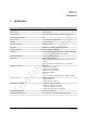
WD105 Datasheet 3. Specification Model Number WD105 Product Type 802.11n perforation IoE module Memory Size 4Mbit of Flash Host Interface(s) SPI, HSIC, USB2.0, SDIO (selectable, see Table 1-5) Embedded MAC Address Yes WiFi Chip(s) Qualcomm Atheros QCA4002 Package 27-pin perforation Wireless Standard(s) IEEE 802.11b/g/n Spreading IEEE 802.11b DSSS and 802.11g/n OFDM Operating Frequency 2412~2484MHz ISM band Antenna On-board PCB antenna.
WD105 Datasheet Model Number WD105 Power Requirements (typical) Tx mode : 11Mbps: 240mA 54Mbps: 210mA 72.2Mbps: 220mA Rx mode : 11Mbps: 62mA 54Mbps: 62mA 72.2Mbps: 62mA Dimensions 25 x 20 x 2.6 ±0.
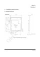
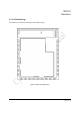
WD105 Datasheet 4. Mechanical Characteristics 4.
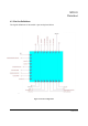
WD105 Datasheet 4.2 Pin Out Definitions The logical definitions of the module’s pins are depicted below.
WD105 Datasheet 4.3 Pad Numberings Pin numbers are defined according to the following map.
WD105 Datasheet 4.4 Pad Size Pin numbers are defined according to the following map.
WD105 Datasheet 4.5 Pin Definitions This section describes module signals and the associated pins. Table 1: Pin Definitions Pin No. Pin name Description Genernal Type 1 Ground Ground P 2 VDDIO_SDIO Connect to 3.3V host I/O supply or 1.8V peripheral I/O supply P 3 UART1_CTS|TDO UART Clear to Send O 4 TCK|I2C_CLK I2C Clock 5 UART1_TXD|TESTMODE UART1 Series Output. O 6 UART1_RXD|TMS UART1 Series intput.
WD105 Datasheet Pin No. Pin name Description Genernal Type 24 UART2_TXD|I2S1_SDI UART2 Series Output. O 25 UART2_RXD|TRST_7x7|I2S1_SDO UART2 Series Input.
WD105 Datasheet Table 1-3: Pin Definitions : I2S Pin No. Pin name Interface function3 function3 type 8 SPI_CLK|SD_CLK|I2S2_MCK I2S2 MCK 11 SPI_MISO|SD_DATA0|I2S2_WS|JTAG_EN I2S2 WS 14 SPI_INT|SD_DATA1|I2S2_SDO I2S2_SDO O 15 SD_DATA2|I2S2_SDI|HM0 I2S2_SDI I 16 SPI_MOSI|SD_DATA3|I2S2_BCK I2S2_BCK I/O 22 I2S1_WS|TRST_8x8 I2S1_WS I 24 UART2_TXD|I2S1_SDI I2S1_SDI I 25 UART2_RXD|TRST_7x7|I2S1_SDO I2S1_SDO O I/O Table 1-4: Pin Definitions : JTAG Pin No.
WD105 Datasheet 5. Block Diagram Figure 5: Block Diagramn 6. Warranty One year limited warranty.
WD105 Datasheet 7. Package and Assembly Notes 7.1 Reel Specifications The following diagram depicts the reel specifications in shipping WD105. (TBD) Figure 6: Reel Specifications 7.2 Carrier Specifications The following diagram depicts the carrier specifications in shipping WD105.
WD105 Datasheet 7.3 Tape PET Cover Specification The following diagram depicts the Tape PET Cover specification in shipping WD105. (TBD) Figure 8: Tape PET Cover Specification 7.4 Tape Protection Ribbon The following diagram depicts the Tape Protection Ribbon specification in shipping WD105. (TBD) Figure 9: Tape Protection Ribbon 7.5 Packing Instruction The following diagram depicts the packing instruction specification in shipping WD105.
WD105 Datasheet Figure 10: Packing Instruction 17 2014-03-20
WD105 Datasheet 7.6 Aluminum Bag Label The following diagram depicts the Aluminum bag label specification in shipping WD105. (TBD) Figure 11: Aluminum Bag Label 1 7.7 White Box Label and Aluminum Bag Label (TBD) Figure 12: Box Label Table 2: White Box Label Specification (TBD) 7.
WD105 Datasheet 7.9 Pallet Specification 7.9.1 Pallet Dimensions The following table the pallet specification in shipping WD105. Table 4: Pallet Dimensions Specification Shipping ways Pallet Size W x L x H Air Shipment 113cm x 120cm x 12cm (recommended) Sea Shipment 113cm x 120cm x 12cm (recommended) 7.9.2 Max. Height The following table the max. height specification in shipping WD105. Table 5: Max.
WD105 Datasheet 7.9.3 Pallet Packaging a). V-boards and strapping: a-1. Put 4 V-boards on the four side corners to prevent cartons collapse. a-2. Put 4 V-boards on the four top edges. a-3. Fix the unit by at least 2 pieces of PP straps. b). Wrapping: b-1. Put 3 layers at least on each surface. b-2. Carton logo need to be recognized if over 3 layers. b-3. Make sure not to tighten too much as it can damage he loads. b-4. Need to seal the top layer with wrap.
WD105 Datasheet 8. Regulatory Information 8.1 FCC Notice (USA) This device complies with Part 15 of the FCC Rules. Operation is subject to the following two conditions: (1) This device may not cause harmful interference, and (2) this device must accept any interference received, including interference that may cause undesired operation. This equipment has been tested and found to comply with the limits for a Class B digital device, pursuant to Part 15 of the FCC Rules.
WD105 Datasheet This device is intended only for OEM integrators under the following conditions: 1) The antenna must be installed such that 20 cm is maintained between the antenna and users, and 2) The transmitter module may not be co-located with any other transmitter or antenna. As long as 2 conditions above are met, further transmitter test will not be required.
WD105 Datasheet 8.