
User's Manual

COMPANY CONFIDENTIAL
7
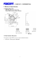
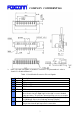
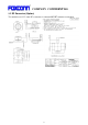
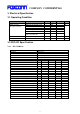
Here is the pin-out signals of module’s connector. The pin number is refer to
“Item2.2.1 module dimension”.
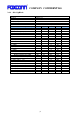
Table 1: Host-Module Connector Pin-out Signals
No.
Pin-Out Description
1
VCC
VCC 5V
2 GND GND
3 DN USB Data DN
4 DP USB Data DP
5 GND GND
6 Reset Reset (active low, input)
Once asserts low, all digital logic in the chip is reset to default
power up states. This pin has internal pull-up resistor on module.
7 Wakeup GPIO interrupt (host-to-chip wakeup interrupt) (input) (default)
Host Wakeup: chip-to-host wakeup interrupt (output)
8 PDn Full Power Down (active low, input)
This pin has internal pull-up resistor on module.