
Umdas 0802DA USB Data Acquisition Module 8 Channels of 48kHz 13-bit A/D, 16 DIO, with 2 channels of 12-bit D/A User's Manual

In differential mode, the following two requirements must be met for linear operation:
! Any analog input must remain in the −10V to +20V range with respect to ground at all times.
! The maximum differential voltage on any given analog input pair must remain within the selected voltage
range.
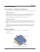
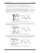
The input [common-mode voltage + signal] of the differential channel must be in the
−10 V to +20 V range in order to yield a useful result. For example, you input a 4 V pp sine wave to CHHI, and
apply the same sine wave 180° out of phase to CHLO. The common mode voltage is 0 V. The differential input
voltage swings from 4 V− (−4 V) = 8 V to (−4 V) − 4 V = −8V. Both inputs satisfy the
−10 V to +20 V input range requirement, and the differential voltage is suited for the ±10 V input range (see
). Figure 3-5
Figure 3-5. Differential voltage example: common mode voltage of 0 V
+4V
-4V
+4V
-4V
0V
CHLO
CHHI
+/-8V
8V Differential
Measured Signal
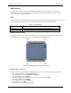
If you increase the common mode voltage to 11 V, the differential remains at ±8 V. Although the [common-
mode voltage + signal] on each input now has a range of +7 V to +15 V, both inputs still satisfy the −10 V to
+20 V input requirement (see ). Figure 3-6
Figure 3-6. Differential voltage example: common mode voltage of 11 V
+11V
+7V
+11V
+/-8V
+15V
8V Differential
CHLO
CHHI
Measured Signal
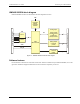
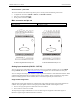
If you decrease the common-mode voltage to −7 V, the differential stays at ±8 V. However, the solution now
violates the input range condition of −10 V to +20 V. The voltage on each analog input now swings from −3V
to −11V. Voltages between −10 V and −3 V are resolved, but those below -10 V are clipped (see ). Figure 3-7
Figure 3-7. Differential voltage example: common mode voltage of -7 V
-3V
-11V
-7V
+/-7V
8V Differential
-11V
-7V
-3V
3V
CHLO
CHHI
Measured Signal
3-5
UMDAS 0802DA User's Guide Functional Details