
Umdas 0802DA USB Data Acquisition Module 8 Channels of 48kHz 13-bit A/D, 16 DIO, with 2 channels of 12-bit D/A User's Manual
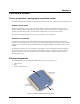

Screw terminal – pins 21-40
The screw terminals on the bottom edge of the (pins 21 to 40) provide the following connections:
! 16 digital I/O connections (
PortA0 to Port A7, and Port B0 to Port B7)
! One power connection (
PC+5 V)
! Three ground connections (
GND)
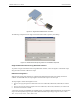
Main connector and pin out
Connector type Screw terminal
Wire gauge range 16 AWG to 30 AWG
20 CTR
19 SYNC
18 TRIG IN
17 GND
16 +2.5VREF
15
14 D/A OUT 1
13 D/A OUT 0
12
11
10
9
8
AGND
AGND
CH7 IN
CH6 IN
AGND
CH5 IN
7 CH4 IN
6AGND
5 CH3 IN
4 CH2 IN
3AGND
2 CH1 IN
1 CH0 IN
GND 40
GND 31
PC +5 V 30
GND 29
Port A7 28
Port B7 39
Port B6 38
Port B5 37
Port B4 36
Port B3 35
Port B2 34
Port B1 33
Port B0 32
Port A6 27
Port A5 26
Port A4 25
Port A3 24
Port A2 23
Port A1 22
Port A0 21
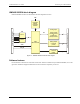
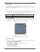
8-channel single-ended mode pin out
20 CTR
19 SYNC
18 TRIG_IN
17 GND
16 +2.5VREF
15
14 D/A OUT 1
13 D/A OUT 0
12
11
10
9
8
AGND
AGND
CH3 IN LO
CH3 IN HI
AGND
CH2 IN LO
7CH2 IN HI
6AGND
5CH1 IN LO
4CH1 IN HI
3AGND
2CH0 IN LO
1CH0 IN HI
GND 40
GND 31
PC +5 V 30
GND 29
Port A7 28
Port B7 39
Port B6 38
Port B5 37
Port B4 36
Port B3 35
Port B2 34
Port B1 33
Port B0 32
Port A6 27
Port A5 26
Port A4 25
Port A3 24
Port A2 23
Port A1 22
Port A0 21
4-channel differential mode pin out
Analog input terminals (CH0 IN - CH7 IN)
You can connect up to eight analog input connections to the screw terminal containing pins 1 to 20 (CH0 IN
through
CH7 IN.) Refer to the "Main connector and pin out" diagrams above for the location of these pins.
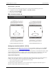
You can configure the analog input channels as eight single-ended channels or four differential channels. When
configured for differential mode, each analog input has 14-bit resolution. When configured for single-ended
mode, each analog input has 13-bit resolution, due to restrictions imposed by the A/D converter.
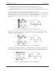
Single-ended configuration
When all of the analog input channels are configured for single-ended input mode, eight analog channels are
available. The input signal is referenced to signal ground (GND), and delivered through two wires:
! The wire carrying the signal to be measured connects to CH# IN.
! The second wire connects to AGND.
The input range for single-ended mode is ±10 V. No other ranges are supported in this mode. Figure 3-3
illustrates a typical single-ended measurement connection.
3-3
UMDAS 0802DA User's Guide Functional Details