® Data Acquisition UMDAS 0802DA USB Data Acquisition Module - 8 Channels of 48kHz 13-bit A/D, 16 DIO, with 2 channels of 12-bit D/A USER’S MANUAL VER. 1.1 • January 2006 No part of this manual may be reproduced without permission ® CyberResearch , Inc. www.cyberresearch.com 25 Business Park Dr.
® CyberResearch Data Acquisition UMDAS 0802DA ©Copyright 2006 All Rights Reserved. January, 1 2006 The information in this document is subject to change without prior notice in order to improve reliability, design, and function and does not represent a commitment on the part of CyberResearch, Inc. In no event will CyberResearch, Inc.
® CyberResearch Data Acquisition UMDAS 0802DA Intentionally Blank iv ©Copyright 2006 CyberResearch, Inc.
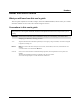
Table of Contents Preface About this User's Guide ......................................................................................................................vi What you will learn from this user's guide ........................................................................................................vi Conventions in this user's guide ........................................................................................................................
UMDAS 0802DA User's Guide Non-volatile memory...................................................................................................................................... 4-5 Microcontroller............................................................................................................................................... 4-5 Power..............................................................................................................................................................
Preface About this User's Guide What you will learn from this user's guide This user's guide explains how to install, configure, and use the UMDAS 0802DA, and also refers you to related documents available on our web site, and to technical support resources. Conventions in this user's guide For more information on … Text presented in a box signifies additional information and helpful hints related to the subject matter you are reading.
Chapter 1 Introducing the UMDAS 0802DA This user's guide contains all of the information you need to connect the UMDAS 0802DA to your computer and to the signals you want to measure. The UMDAS 0802DA is part of the CyberResearch™ brand of USBbased data acquisition products. The UMDAS 0802DA is a USB 2.0 full-speed, device that is supported under popular Microsoft® Windows® operating systems. The UMDAS 0802DA is fully compatible with both USB 1.1 and USB 2.0 ports.
UMDAS 0802DA User's Guide Introducing the UMDAS 0802DA UMDAS 0802DA block diagram UMDAS 0802DA functions are illustrated in the block diagram shown here. USB Full-speed USB 2.0 Compliant Interface Analog Input DIO SPI Port A 8 8 single-ended (13-bit) channels or 4 differential (14-bit) channels 8 Port B USB Microcontroller Analog Output 2 channels (12-bit) SYNC 2 TRIG_IN Event Counter 1 channel (32-bit) Screw terminal I/O connector Screw terminal I/O connector 16 1 Figure 1-2.
UMDAS 0802DA User's Guide Introducing the UMDAS 0802DA Connecting a UMDAS 0802DA to your computer is easy Installing a data acquisition device has never been easier. ! ! ! ! ! ! The UMDAS 0802DA relies upon the Microsoft Human Interface Device (HID) class drivers. The HID class drivers ship with every copy of Windows that is designed to work with USB ports.
Chapter 2 Installing the UMDAS 0802DA What comes with your UMDAS 0802DA shipment? As you unpack your UMDAS 0802DA, verify that the following components are included. Hardware ! UMDAS 0802DA ! USB cable (2 meter length) Additional documentation In addition to this hardware user's guide, you should also receive the Quick Start Guide (available in PDF on the software CD that ships with your device.
UMDAS 0802DA User's Guide Installing the UMDAS 0802DA Unpacking the UMDAS 0802DA As with any electronic device, you should take care while handling to avoid damage from static electricity. Before removing the UMDAS 0802DA from its packaging, ground yourself using a wrist strap or by simply touching the computer chassis or other grounded object to eliminate any stored static charge. If any components are missing or damaged, notify CyberResearch, Inc.
UMDAS 0802DA User's Guide Installing the UMDAS 0802DA The last popup balloon or dialog states "Your new hardware is installed and ready to use," and the LED on the UMDAS 0802DA should flash and then remain lit. This indicates that communication is established between the UMDAS 0802DA and your computer. On most computers, you can install up to two UMDAS 0802DA units.
Chapter 3 Functional Details Theory of operation - analog input acquisition modes The UMDAS 0802DA can acquire analog input data in two different modes – software paced and continuous scan. Software paced mode In software paced mode, you can acquire one analog sample at a time. You initiate the A/D conversion by calling a software command. The analog value is converted to digital and returned to the computer.
UMDAS 0802DA User's Guide Functional Details USB connector The USB connector is on the right side of the UMDAS 0802DA. This connector provides +5 V power and communication. The voltage supplied through the USB connector is system-dependent, and may be less than 5 V. No external power supply is required. LED The LED on the front of the housing indicates the communication status of the UMDAS 0802DA. It uses up to 5 mA of current and cannot be disabled.
UMDAS 0802DA User's Guide Functional Details Screw terminal – pins 21-40 The screw terminals on the bottom edge of the (pins 21 to 40) provide the following connections: ! ! ! 16 digital I/O connections (PortA0 to Port A7, and Port B0 to Port B7) One power connection (PC+5 V) Three ground connections (GND) Main connector and pin out Screw terminal 16 AWG to 30 AWG GND Port B7 Port B6 Port B5 Port B4 Port B3 Port B2 Port B1 Port B0 GND PC +5 V GND Port A7 Port A6 Port A5 Port A4 Port A3 Port A2 Port A1
UMDAS 0802DA User's Guide Functional Details Pin 3 AGND Pin 1 CH0 Figure 3-3. Single-ended measurement connection The following example shows the single-ended measurement data acquired by TracerDAQ. Figure 3-4. Measurement data (9 volt) plotted on TracerDAQ's Strip Chart Single-ended measurements using differential channels To perform a single-ended measurement using differential channels, connect the signal to "CHn IN HI" input, and ground the associated "CHn IN LO" input.
UMDAS 0802DA User's Guide Functional Details In differential mode, the following two requirements must be met for linear operation: ! ! Any analog input must remain in the −10V to +20V range with respect to ground at all times. The maximum differential voltage on any given analog input pair must remain within the selected voltage range. The input [common-mode voltage + signal] of the differential channel must be in the −10 V to +20 V range in order to yield a useful result.
UMDAS 0802DA User's Guide Functional Details Since the analog inputs are restricted to a −10 V to +20 V signal swing with respect to ground, all ranges except ±20V can realize a linear output for any differential signal with zero common mode voltage and full scale signal inputs. The ±20 V range is the exception. You cannot put −20 V on CHHI and 0 V on CHLO since this violates the input range criteria. Table 3-2 shows some possible inputs and the expected results. Table 3-2.
UMDAS 0802DA User's Guide Functional Details Port A0 +GND +5V Figure 3-9. Schematic showing switch detection by digital channel Port A0 For more information on digital signal connections For more information on digital signal connections and digital I/O techniques, available on the software CD which accompanies your device. Power terminals The PC +5V connection (pin 30) draws power from the USB connector. This terminal is a 5 V output that is supplied by the host computer.
UMDAS 0802DA User's Guide Functional Details +2.5VREF terminal The +2.5VREF connection (pin 16) is an output terminal that supplies 2.5 volts. The images below show the +2.5VREF pin configured as the voltage source for channel 0. Single-ended measurement Differential measurement SYNC terminal The SYNC connection (pin 19) is a bidirectional I/O signal. You can use it for two purposes: ! ! Configure as an external clock input to externally source the A/D conversions.
UMDAS 0802DA User's Guide Functional Details Input Voltage +10V Output Code 0 16383 8192 -10V Figure 3-10. Ideal ADC transfer function The offset error is measured at mid-scale. Ideally, a zero volt input should produce an output code of 8192. Any deviation from this is an offset error. Figure 3-11 shows an example of a UMDAS 0802DA transfer function with a ±2.44 mV offset error. Offset error affects all codes equally by shifting the entire transfer function up or down along the input voltage axis.
UMDAS 0802DA User's Guide Functional Details The accuracy plots in Figure 3-12 are drawn for clarity and are not drawn to scale. Input Voltage +10V Gain error = +0.02% or +2 mV Gain error = -0.02%, or -2 mV Ideal Actual Output Code 0 8192 16383 -10V Figure 3-12. ADC Transfer function with gain error Figure 3-12 shows an example of a UMDAS 0802DA transfer function with a calibrated gain error of ±0.02%, or ±2 mV.
UMDAS 0802DA User's Guide Functional Details UMDAS 0802DA channel gain queue feature The UMDAS 0802DA's channel gain queue feature allows you to set up a scan sequence with a unique per-channel gain setting and channel sequence. The channel gain queue feature removes the restriction of using an ascending channel sequence at a fixed gain. This feature creates a channel list which is written to local memory on the UMDAS 0802DA.
UMDAS 0802DA User's Guide Functional Details 4. Select Gated from the Ext. Clock Type drop-down list. 5. Set the Universal Library EXTCLOCK option with cbAInScan()/AInScan for the slave UMDAS 0802DA to enable pacing from the master USB device. This InstaCal option does not affect internally paced acquisition. It only affects scans that use the EXTCLOCK option. An example of a master/slave configuration is shown here.
Chapter 4 Specifications Typical for 25°C unless otherwise specified. Specifications in italic text are guaranteed by design. Analog input Table 4-1.
UMDAS 0802DA User's Guide Specifications Note 2: Maximum throughput scanning to PC memory is machine dependent. The rates specified are for Windows XP only. Maximum rates on operating systems that predate XP may be less and must be determined through testing on your machine Note 3: The ADS7871 converter only returns 13-bits (0 to 8192 codes) in single-ended mode.
UMDAS 0802DA User's Guide Specifications Analog output Table 4-6. Analog output specifications Parameter Conditions Resolution Output range Number of channels Throughput (Note 5) Software paced Single channel, continuous scan Dual channel, continuous scan, simultaneous update Power on and reset voltage Output drive Slew rate Note 5: Specification 12-bits, 1 in 4096 0 to 4.096 V, 1 mV per LSB. 2 250 S/s single channel typical, PC dependent 10 kS/s 5 kS/s 0V, ±20 mV typ.
UMDAS 0802DA User's Guide Specifications External trigger Table 4-10. Digital trigger specifications Parameter Conditions Specification Trigger source (Note 7) Trigger mode External digital Software selectable TRIG_IN Edge sensitive: user configurable for CMOS compatible rising or falling edge. 10 µs max 1 µs min 4.0 V min, 5.5 V absolute max 1.0 V max, –0.5 V absolute min ±1.
UMDAS 0802DA User's Guide Specifications Non-volatile memory Table 4-13. Non-volatile memory specifications EEPROM EEPROM Configuration 1,024 bytes Address Range Access Description 0x000-0x07F 0x080-0x1FF 0x200-0x3FF Reserved Read/write Read/write 128 bytes system data 384 bytes cal data 512 bytes user area Microcontroller Table 4-14. Microcontroller specifications Type Program memory Data memory High performance 8-bit RISC microcontroller 16,384 words 2,048 bytes Power Table 4-15.
UMDAS 0802DA User's Guide Specifications General Table 4-16. General specifications Parameter Conditions Specification Device type Device compatibility USB 2.0 full speed USB 1.1, USB 2.0 Environmental Table 4-17. Environmental specifications Operating temperature range Storage temperature range Humidity 0 to 70 °C –40 to 70 °C 0 to 90% non-condensing Mechanical Table 4-18.
UMDAS 0802DA User's Guide Specifications 8-channel single-ended mode Pin 1 2 3 4 5 6 7 8 9 10 11 12 13 14 15 16 17 18 19 20 Signal Name CH0 IN CH1 IN AGND CH2 IN CH3 IN AGND CH4 IN CH5 IN AGND CH6 IN CH7 IN AGND D/A OUT 0 D/A OUT 1 AGND +2.
® CyberResearch Data Acquisition UMDAS 0802DA Product Service Diagnosis and Debug CyberResearch, Inc. maintains technical support lines staffed by experienced Applications Engineers and Technicians. There is no charge to call and we will return your call promptly if it is received while our lines are busy. Most problems encountered with data acquisition products can be solved over the phone. Signal connections and programming are the two most common sources of difficulty.
® CyberResearch Data Acquisition UMDAS 0802DA Intentionally Blank 32 ©Copyright 2006 CyberResearch, Inc.
® CyberResearch Data Acquisition UMDAS 0802DA Warranty Notice CyberResearch, Inc. warrants that this equipment as furnished will be free from defects in material and workmanship for a period of one year from the confirmed date of purchase by the original buyer and that upon written notice of any such defect, CyberResearch, Inc. will, at its option, repair or replace the defective item under the terms of this warranty, subject to the provisions and specific exclusions listed herein.
® CyberResearch Data Acquisition UMDAS 0802DA Intentionally Blank 34 ©Copyright 2006 CyberResearch, Inc.
CyberResearch, Inc. 25 Business Park Drive Branford, CT 06405 USA P: (203) 483-8815; F: (203) 483-9024 www.cyberresearch.