
User's Manual


Table Of Contents
- 1.1 Overview
- 1.2 General Parameters
- 1.3 Electrical and Thermal Characteristics
- 1.4 Pinout Diagram
- 1.5 Pinout Listing
- 1.6 Package Description
- 1.7 System Design Information
- 1.8 Ordering Information
- A.1 Package Environmental, Operation, Shipment, A....
- A.2 Card Assembly Recommendations
20 603 Hardware Specifications, REV 2
Preliminary—Subject to Change without Notice
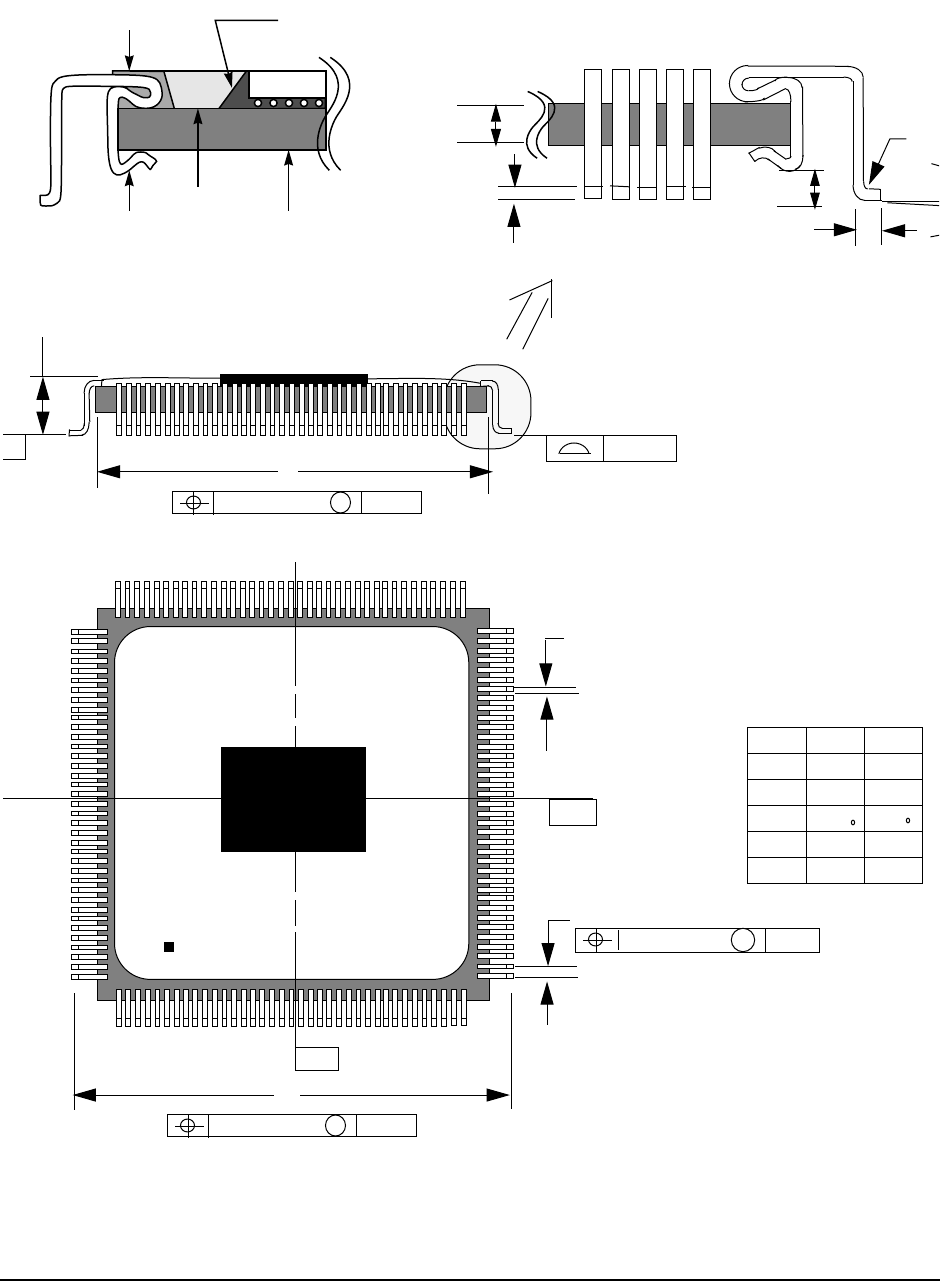
1.6.2.2 Mechanical Dimensions of the IBM C4-CQFP Package
Figure 11 shows the mechanical dimensions for the C4-CQFP package.
Figure 11. Mechanical Dimensions of the IBM C4-CQFP Package
*Reduced pin count shown for clarity. 60 pins per side
Min. Max.
A 31.8 32.2
B 34.4 34.8
C 3.05 3.15
D 0.45 0.55
E 0.18 0.28
Clip Leadframe
Chip
Tape Cast Ceramic
Epoxy Dam
Urethane
Solder-Bump Encapsulant
H
Jmin
Rad
0.08
F
G
A
B
E
Cmax
0.13 TOTAL
s
A-B
C
-
0.13 TOTAL
s
A-B
0.08 TOTAL
M
A-B
D
-A-
Pin 240
Pin 1
* Not to scale
All measurements in mm
Ang
-B-