User’s Manual CPS3500PIE/CPS3500PRO/CPS3500STD CPS5000PIE/CPS5000PRO/CPS5000STD CyberPower North America CyberPower Systems (USA), Inc. 4241 12th Avenue East Suite 400 Shakopee, MN 55379 Tel: 877-297-6937 Fax: 952-403-0009 Website: http://www.cyberpowersystems.com E-mail: sales@cyberpowersystems.com CyberPower Europe CyberPower Systems B.V. Flight Forum 3545,5657DW Eindhoven,The Netherlands Tel: +31 (0)40 2348170 Fax: +31 (0)40 2340314 Website: http://eu.cyberpowersystems.com/ E-mail: sales@cyberpower-eu.
CPS3500&CPS5000 Series Content SAFETY AND EMC INSTRUCTION................................................ 2 INSTALLING YOUR EPS............................................................... 4 UNPACKING .....................................................................................................4 AUTOMATIC VOLTAGE REGULATOR ................................................................4 HARDWARE INSTALLATION GUIDE ...................................................................4 DESCRIPTION ..
CPS3500&CPS5000 Series SAFETY AND EMC INSTRUCTIONS Safety and EMC instruction This manual contains important safety instructions. Please read and follow all instructions carefully during installation and operation of the unit. Read this manual thoroughly before attempting to unpack, install, or operate your Emergency Power System (EPS). CAUTION! To prevent the risk of fire or electric shock, install in a temperature and humidity controlled indoor area free of conductive contaminants.
CPS3500&CPS5000 Series DO NOT USE FOR MEDICAL OR LIFE SUPPORT EQUIPMENT! DO NOT use in any circumstance that would affect operation or safety of any life support equipment or with any medical applications or patient care. DO NOT USE WITH OR NEAR AQUARIUMS! To reduce the risk of fire or electric shock, do not use with or near an aquarium. Condensation from the aquarium can cause the unit to short out.
CPS3500&CPS5000 Series INSTALLING YOUR EPS Installing your EPS UNPACKING Inspect the EPS upon receipt. The box should contain the following: EPS unit x1; Installation Guide x1; User manual x1; Battery Wiring Arrangement manual x 1; AUTOMATIC VOLTAGE REGULATOR When utility power is inconsistent, the EPS would increases low voltage or decrease high voltage to safe 220 volts.
CPS3500&CPS5000 Series BASIC OPERATION operation CPS3500PRO/CPS5000PRO DESCRIPTION CPS3500PIE/CPS3500STD CPS5000PIE/CPS5000STD * STD Series only use soft pad 1. AC Outlets EPS PRO/PIE Series have two general plug-in outlets (UK/Schuko/ France) and one terminal outlet for connected equipment which ensures temporary uninterrupted operation of the equipment during a power failure. Max. Output of 1a is 40A ; Max. Output of 1b is 12A for UK socket, 16A for Schuko/France socket. Max.
CPS3500&CPS5000 Series *Note: Circuit breaker 5a provides max 40A protection for 1a socket. *Note: Circuit breaker 5b provides max 12A protection for UK socket or 16A for Schuko and France socket. 6. AC Input Circuit Breaker Located on the side of the EPS, the circuit breaker serves to provide overload and fault protection. 7. Battery Input Wiring Fault LED Battery input wiring fault LED will illuminate and make an audible alarm to indicate the wiring polarity is reversed. 8.
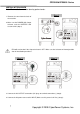
CPS3500&CPS5000 Series INSTALLATION GUIDE Note: The installation must be done by professionals. 1. Remove the cover from the back of the machine. Step 1 2. Make sure the POWER SW, Output Selector, and the BATTERY SW. are turned off. (Step1) EPS will not function if the Output Selector is OFF. Make sure the Selector on Normal position after all installation procedures. Step 2 Step 3 3. Connect the AC OUTPUT connections (AC plugs or terminal connections). (Step2) 4.
CPS3500&CPS5000 Series Step 4 Step 5 5. Connect the batteries to the BATTERY INPUT. (Step4) WIRING FAULT LED will illuminate and make an audible alarm to indicate the wiring polarity is reversed. 6. If the battery box or the battery connection has a switch, please turn it on first. 7. Turn on the BATTERY SW. on the back of the machine (Step 5) 8. Turn on the Power Switch and switch the Output Selector to Normal on the front panel. The Power On Indicator and the LCD Module Display will blink 4 times.
CPS3500&CPS5000 Series REPLACING THE BATTERY Replacing the battery CAUTION! Read and follow the IMPORTANT SAFETY INSTRUCTIONS before servicing the battery. Battery service should only be done by qualified professionals. CAUTION! Use only the specified type and number of external batteries. Please see the technical specifications for replacement batteries. CAUTION! The battery may present a risk of electrical shock. Do not dispose of battery in a fire as it may explode.
CPS3500&CPS5000 Series DEFINITIONS FOR ILLUMINATED LCD Definitions for illuminated LCD The LCD Display indicates a variety of EPS operational conditions. All descriptions apply when the EPS is plugged into an AC outlet and turned on or when the EPS is on battery. 1. INPUT VOLTAGE Meter: This meter measures the AC voltage that the EPS is receiving from the utility wall outlet.
CPS3500&CPS5000 Series CyberPower Systems for further help and support. 10. BATTERY CAPACITY Meter: This meter displays the approximate charge level (in 20% increments) of the EPS's external battery. During a blackout or severe brownout, the EPS will switch to battery power, the ON BAT icon will be illuminated, and the charge level will decrease. 11. LOAD CAPACITY Meter: This meter displays the approximate output load level (in 20% increments) of the EPS's battery outlets.
CPS3500&CPS5000 Series setting is 200AH. Function description: The charger will automatically adjust current to setting value. c. Nominal Output Voltage: Configures the correct electricity/voltage supplied in the area/country where the EPS will be used. 220V, 230V and 240V may be selected. The system default setting is 220V. Function description: AVR Dynamic Voltage Compensation works automatically based on the system voltage settings. d.
CPS3500&CPS5000 Series FAULT WARNING DISPLAY AND ALARM Fault warning display and alarm 1. 2. :The machine shut down and the LCD display output voltage is zero. Over-Load Protection:The machine shut down and Over Load and FAULT Icon lights on the LCD Overheat Protection display. :The machine sounds long and rapid beep and Battery icon flashes. 3. Battery Missing 4.
CPS3500&CPS5000 Series TROUBLESHOOTING Trouble shooting Problem Possible Cause Circuit breaker has tripped due to an overload. Outlet does not provide power to equipment. Batteries are discharged. Unit has been damaged by a surge or spike. The EPS will not turn on. Uncritical outlets have turned off automatically due to an overload. The on/off switch is designed to prevent the damage that rapidly turns it off and on. The unit is not connected to an AC outlet. The battery is worn out.
CPS3500&CPS5000 Series TECHNICAL SPECIFICATIONS Technical specifications Model CPS3500PIE CPS3500PRO CPS3500STD CPS5000PIE/ CPS5000PRO CSP5000STD Capacity (VA) 3500VA 3500VA 5000VA 5000VA Capacity (Watts) Operation Technology 2450W 2450W 3500W AVR ( Single Boost & Single Buck ) AC Input Input Voltage Range 2450W 140Vac – 300Vac Input Frequency Range AC Output 50/60 Hz +/- 5 Hz (auto sensing) Phase On Battery Typical Output Voltage Single Phase Pure Sine Wave at 220Vac +/- 5% Nominal Out
CPS3500&CPS5000 Series Copyright © 2009 CyberPower Systems, Inc.
CPS3500&CPS5000 Series For more information, contact us at: CyberPower North America CyberPower Systems (USA), Inc. 4241 12th Avenue East Suite 400 Shakopee, MN 55379 Tel: 877-297-6937 Fax: 952-403-0009 Website: http://www.cyberpowersystems.com E-mail: sales@cyberpowersystems.com CyberPower Europe CyberPower Systems B.V. Flight Forum 3545,5657DW Eindhoven,The Netherlands Tel: +31 (0)40 2348170 Fax: +31 (0)40 2340314 Website: http://eu.cyberpowersystems.com/ E-mail: sales@cyberpower-eu.